Technical Information
Key Components
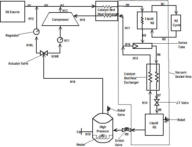
The description above (see The Basics) goes over a simplified process for the liquefaction of hydrogen. The image to the left displays the original design’s flow diagram, with the process labeled in order from start (H1) to finish (H19). Ultra high purity hydrogen is supplied by either an hydrogen generator or steam methane reformer at an operating pressure of 1400 psi (H1). This hydrogen enters a catalyst bed heat exchanger (H3), then enters the liquid nitrogen bath (H4) where it is cooled to a temperature of ~77º K. When the cooled hydrogen exits the bath it enters our patent pending vortex tube (H5) where the “hot” hydrogen exits one end of the vortex tube (H16) and cold hydrogen exits the other end (H6). Cold hydrogen enters a second catalyst bed heat exchanger where it exits close to the liquefaction temperature (H7) and is expanded via J-T valve (H8) in order to fully liquefy. The initial liquid hydrogen is then temporarily stored in the first tank before being pumped into the high pressure storage tank (H9) used for dispensing.
Boil off from the first tank is used to pre-cool hydrogen exiting the “cold” end of the vortex tube (H14). This boil off is then mixed with the hydrogen gas exiting the “hot” end of the vortex tube where it is used to pre-cool hydrogen in the first catalyst bed heat exchanger (H17) before entering the compressor (H18). The boiling of liquid hydrogen is used in our patent pending cryogenic thermal compression system to pressurize the fill tank to the necessary dispensing pressure of ~10000 psi before fueling.
Once the fuel has been dispensed (H19) excess pressure in the tank is vented into an actuator valve (H10) then regulator (H10L) where it is reintroduced into the system at the necessary 1400 psi (H12). When the pressure released from the fill tank drops below 1400 psi the actuator valve will flip (H10R), gas will flow through a pressure regulator (H11) into the compressor where the hydrogen will be returned to 1400 psi (H13).
