Piping and Fittings Team

Hello! We are the WSU H2 – Refuel Hydrogen Piping and Fitting team
Left to Right: Ibrahim Alazri – Brett Love – Wyatt Linville – Malcolm Wynn – Daniel Pollastro
Background
Transporting liquid hydrogen throughout the fueling station has its complications. One of the problems is hydrogen embrittlement to a material over time. If the material chosen for pipes absorbs the hydrogen, then the material will succumb to brittle failures because of the change in characteristics. More can be learned about hydrogen embrittlement here. To combat this problem, materials that are not affected by hydrogen embrittlement need to be used. These are the materials that we have to choose from.
Copper: Using copper prevents the hydrogen embrittlement from occurring. This material is abundant, cost effective, and can be machined and processed at a reasonable price.
Stainless Steel: Choosing this material would also prevent hydrogen embrittlement from happening. However, stainless steel would cost more than copper both per unit and for machining and processing.
The pipes will be connected and interlocked throughout the station with fittings. These were chosen to optimize the efficiency of our system. Fittings are easily replaced and also allow ease of maintenance for the station when problems occur. The types of fittings we have narrowed down to are:
VCR Compression Welded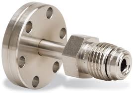
VCR: VCR fittings are zero clearance, high purity fittings that allow the interconnects to be leak tight while also providing ease of assembly and disassembly. The fittings must be welded to other parts, which would increase the cost.
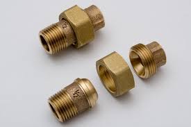
Compression: Compression fittings are an inexpensive alternative that does not require welding. They allow reuse of fittings and tubing. Although the fittings are not zero clearance, they are easily disassembled and reassembled.
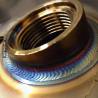
Welded: Welded connections are the industry standard. They are leak-proof and are the strongest fitting type. Welded connections do not allow for ease of maintenance, since the connections must be cut and re welded every time.
Here is the current system design with all of the interconnections labeled:
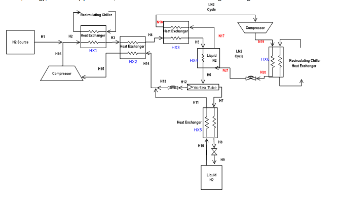
Each connection for our system will be using 316 Stainless Steel for piping with a half inch inside diameter. These pipes will be fitted with the same compression fitting between each connection. However, for insulating the connections of each subsystem, Fiberfrax insulating blanketing will be used between the Source, the Compressor and the first Heat exchanger as this area is outside of the Cryogel Z area of operation. This blanketing is not very efficient, it is mainly there as a safety concern as well as to direct most of the heat to the heat exchanger. Every other section of the system will be insulated with the Cryogel Z.
Introduction
Just like the internet, your system is only as good as your connections. This is why piping and fittings are the most important component of any fluid system. Leaks are most likely to occur at the fittings and are inevitable in any fueling station. This can lead to long shutdown times and in extreme cases of catastrophic failure. Our mission is for the system to immediately detect leaks, resulting in a temporary shutdown in which the necessary repairs can be done. Repairs will be much faster than typical fueling stations due to the modular design. This will result in shorter lag times, which is ideal because when the fueling station is not running it’s not making money.
Paradigms
High-Temperature Syngas & Low-Temperature Liquid Hydrogen
We started off by finding materials to contain and transport the syngas from AgEnergy and the liquid hydrogen with which our system would be interacting. This presented us with a challenge, because the syngas was estimated to be entering our system at 400 degrees Celsius and hydrogen doesn’t liquefy above 33 K. With that in mind, we came up with three materials, with the possibility of using a combination of them: carbon steels, microalloyed steels, and fiber-reinforced polymers. Carbon steels, being the most common, would be the cheapest option, however it would suffer from hydrogen embrittlement, a phenomenon you can find more information here. Microalloyed steels, more specifically stainless steel 316L, would be able to cover the full range of temperatures. In addition, it would be strong because it is also classified as a high-strength, low-alloy steel. The advantage of this material is that we would have just one pipe material throughout the system, however, this would be more expensive. Fiber-reinforced polymers would ensure minimal leakage of the liquid hydrogen. The low melting temperature of the material would mean it could not be used to transport the syngas.
Liquid Hydrogen Connections
Next, we shifted our attention to the liquid hydrogen connections. Hydrogen, being the smallest element, is so small that an atom of hydrogen is about 3.7 times smaller than a water molecule. That’s like comparing a raquetball to a bowling ball. For these connections: we came up with two types: Bayonet and VCR connections. Bayonet connections are named after the way a bayonet is attached to a musket, which is by pushing down and then turning one end in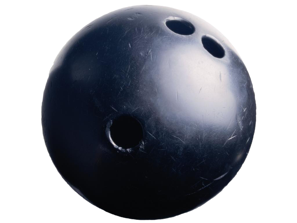 place. Like the soldiers who were untrained and had a quick way to attach their bayonet, we would have a just-as-easy connection with our liquid hydrogen in addition to it being leak-tight. The VCR connections would also be leak-tight. They involve multiple
 ![]() components that work to tighten together. Because there are multiple components, the cost would be higher.
components that work to tighten together. Because there are multiple components, the cost would be higher.
High-Pressure, Gaseous Hydrogen
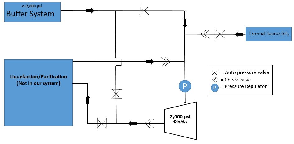
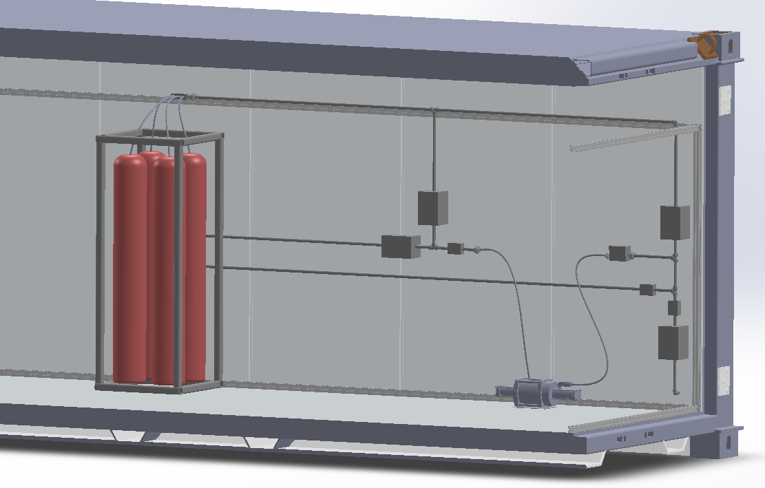
Finally, we focused on the transport of gaseous hydrogen throughout our system. We decided to go with compression connections because of they are cheap, off-the-shelf, and they require less components.We realized that we would need to come up with a layout that could satisfy our goal of connecting an external hydrogen source to the compressor, the buffer system as needed and feed the compressed hydrogen to the liquefaction and purification processes, using the buffer system as just that: a buffer. To this end, we came up with a system diagram that maps out our system and gives a schematic for the essential components, which include automated pressure valves, a pressure regulator, and check valves. The System Diagram is shown below on the left, and the corresponding CAD model is on the right.
Update: Moving forward, we might also have to provide a line from the buffer tanks to a hydrogen fuel cell. The purpose of this fuel cell would be, in case of an emergency power outage, it would slowly utilize the hydrogen gas in the tanks and lines to run the ventilation and sensing components of our system for at least 24 hours. This way, when the fuel cell runs out of fuel, there would be little to no hydrogen in the lines, so the ventilation and sensing would no longer be required.
By our judgement, this change would only add some tubing, a pressure regulator, and possibly some connectors, and would not change the overall schematic of our system.
Implementation:
For our system, we will need a variety of materials. We will need:
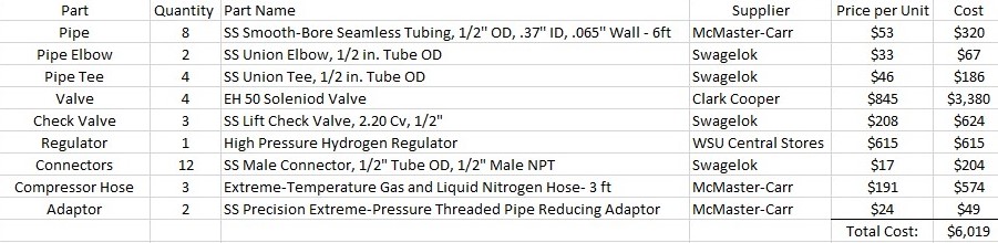
These components are in compliance with the safety standard ASME sections B16.5, B31.12, B31.3, B31.8, and Y14.5. As evident from the table above, the total cost of this part of the project will amount to about $6,019.
Integration:
As the project comes to completion, we will be working with these teams to ensure a smooth installation:
- System Integration Team:
We will be working with System Integration to finalize the layout of the container, and get more precise measurements as the rubber meets the road and theory becomes reality during installation.
- Storage/Compressor Teams:
We will be working with these teams to provide proper connections between our piping and their component.
- Leak Detection Team:
We will be working with this team to ensure minimal leakage to prevent 0.6% hydrogen in the air.
Objective
The main objectives that the Piping and Fittings team will be accomplishing are to ensure the safety between all interconnects within the subsystems of our hydrogen refuel station. This includes the different types of piping needed for each connection, as well as specific fittings that will be used to keep a closed system and to prevent any hydrogen leaking.
Design Requirements
Customer Requirements:
- Safety regulations
- Reliability
- Low manufacturing costs
Key Characteristics:
- Ease of Maintenance
- Weight and size
Design Specifications
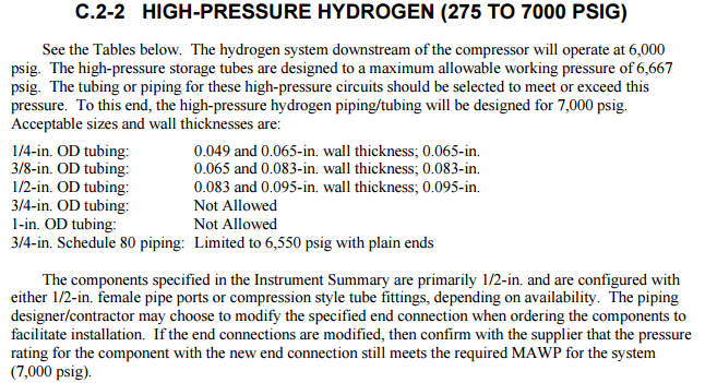
In order to specify the pipes material and size, we should know the pressure and temperature ranges of the flow that will flow inside the pipes. Specifications and standards are created in order to build piping system that would be acceptable. Here is Appendix C – Gaseous Hydrogen Piping Specifications that provides great information on choosing materials, pipe diameters, and thickness for varies pressures. Hydrogen flow is categorized as low pressure, pressure lower than 275 psig, and high pressure, which is pressure range between 276 psig to 7000 psig. Moreover, by following the standards and tables, you can define the appropriate pipe sizing and material. There is also more specification for fittings, joints, and pipe bending. Here are more standards and regulations that can be used for designing our hydrogen gas station’s pipes:
- ASME B31.12 – 2011 – Hydrogen Piping and Pipelines
- ASME B31.1 – 2012 – Power Piping
3. ASME B31.2 – 1968 – Fuel Gas Piping
4. ASME B31.3 – 2012 – Process Piping
- ASME B31.4 – 2012 – Pipeline Transportation Systems for Liquid Hydrocarbons and Other Liquids
- SAE J2601 – Fueling Protocols for Light Duty Hydrogen Surface Vehicle
- SAE J1799 – Hydrogen Surface Vehicle to Station Communication Hardware and Software
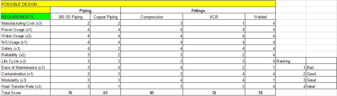
Design Options
Piping
Stainless Steel
Pros
- Can withstand higher temperatures and pressures with a thinner wall thickness compared to copper.
- Has a lower heat transfer coefficient than copper
Cons
- High cost compared to copper
- More difficult to plumb
Copper
Pros
- Better work-ability over stainless
- Lower cost than stainless
Cons
- Higher heat transfer throughout the pipe especially at cryogenic temperatures
- Thicker cross-sectional area than stainless required to withstand pressures
Fittings
Compression
Pros
- Lower cost over VCR fittings.
- Easy to integrate sensors.
- Easy to install and maintain.
- Works best with modular design.
Cons
- Non-zero clearance
- Greater risk of contamination
VCR
Pros
- Best for zero clearance.
- Good for modular design.
Cons
- Easily damaged
- High installation cost
Welded
Pros
- Ideal seal
- Best longevity
- Lowest cost.
Cons
- Not modular
- Not easily serviced
Economics
Initial Projected cost ~ 10,000 USD
This cost is coming from the below information about standard piping and compression fittings, as well as interconnecting vacuum jacketed piping and fittings.
McMaster Carr #2057K11 1/2″ 6′ long unthreaded 316 Stainless Steel Schedule 160 piping is 112.69 USD each as of 12/9/2015.
From the current rough piping CAD drawings we are assuming that we will need roughly 70′ of piping. So we are assuming the final need will be likely 120′.
This will be 2253.80 USD.
Swagelok Part #55-810-6-8W 1/2″ Tube socket weld union is 26.19 USD each as of 11/17/2015.
From current CAD files and estimates we expect to need no less than 90 unions.
This is 2357.10 USD
Global Industrial Part #T9FB301994 72″ 316 stainless vacuum jacketed piping is 222.95 USD each as of 11/17/2015.
We are anticipating to put vacuum jacketed piping in at every interconnect to help with vibration and stress during transport and contraction during operation. We are assuming we need 25 of these.
This will be 5573.75 USD
Totals to 9517.85 USD, but for ease we will assume 10,000 USD
Annual Maintenance Cost ~ 2,300 USD
If the fittings have a hypothetical fail rate of 50% (45 fittings) will be a 1178.55 USD annual fittings cost.
If the vacuum jacketed flex tubing fails at a hypothetical 20% (5 fittings) will cost 1114.75 USD annually.
This will total 2,293.30 USD, or about 2300.00 USD.
Present worth ~ 36,928 USD
This needs to be set aside now to pay for the piping and fittings with 10 years of maintenance with a 6% interest rate.
Depreciation ~ 100%
All fittings will need to be scraped after use as they are a one time use part.
Unless another use could be found, the piping will be scraped as they will have custom bends throughout.
All vacuum jacketed flex tubing should have the ability to be resold as used, or reused in a different application given that the lines are in good working condition.
From pricing found online, a generous 316 Stainless Steel recycling price is roughly $0.50/lb. Each 6′ section weighs roughly 8lbs. With 20 sections needed, that results in roughly 80 USD in recycling.
Recomendations
For piping throughout the system we recommend the use of stainless steel for material. It will lead to lower costs of operation due to less heat loss, and has a higher longevity cyclic environmental loading capability. For the system interconnects we recommend the use of vacuum jacketed flex tubing to provide relief with vibration and stress during transport and contraction during operation.
Due to the desire for a modular design we are choosing to use Swagelok Cryogenic Compression Fittings. These give us all around reliability, cost benefit, and ease of maintenance.
Future
The next steps that the future class should take is to contact Swagelok to have them specify piping and fitting locations within the container once the final designs are in. Swagelok is the preferred company to run all of the piping and make the necessary connections because of our experience with their quick turn around and wealth of technical information.