Energy & Power Consumption
We will be using EES (engineering equation solver) to mathematically map our system. This program uses thermodynamic properties and laws to ensure our system will function from component to component. This includes energy balance equations and mass balance equations when applicable. Here is a link to the EES website if you wish to learn more about their program ( http://www.fchart.com/ees/). We also developed a basic properties chart to ensure neighboring components have matching states as pictured below:
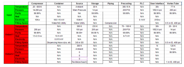
We have chosen the respective individual components after ensuring that our states matched up. We then used EES to model our entire system and evaluate its performance as a whole. ***EES Solved the mass, energy, and entropy balances, for all the streams in our system
The overall power consumption for compression in the main cycle is 42.5 kW, with 5.6 kW of heat exhausted to the Liquid Nitrogen Cycle.
Our entire system will be functioning out of a Light Air Mobile Shelter by Insitu. This container has the capacity rating and specifications as follows in the given table:

These specifications do not encompass the possibilities of having components that are not fastened to the ground but that are instead suspended in air. Further research and planning of the most efficient way to setup our container is undoubtedly needed. We do know though that we will not have enough floor space to fit each component and our current plan for this is to bolt components that will not experience vigorous movements to the ceiling and walls of our container. Large and movement prone components such as our compressor will have to be fastened in the most secure way, which in our case will be the floor.
System Flow
System Flow Diagram: 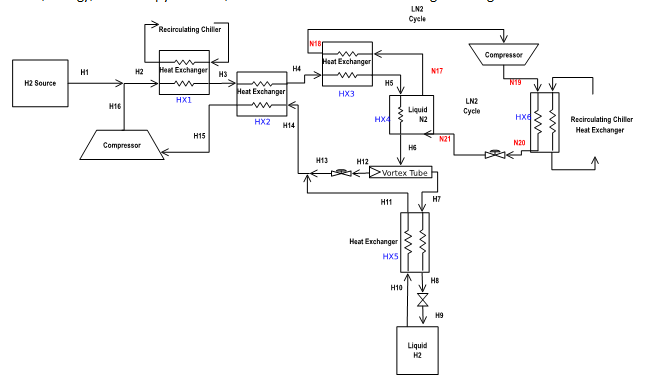
National Electrical Codes
Electrical devices used in hazardous areas need to be certified for use according the requirements specified for the area for this project. In general hazardous locations in North America are separated by classes, divisions, and groups to define the level of safety required for equipment installed in these locations.
The classes define the general nature of hazardous material in the surrounding atmosphere. Class I is a general nature of hazardous material for this project because flammable gases or vapors are present in the air in quantities sufficient to produce explosive or ignitable mixtures.
The division defines the probability of hazardous material being present in an ignitable concentration in the surrounding atmosphere. Division 2 is the probability of hazardous material being present in n ignitable concentration in the surrounding atmosphere in this project, because the substance referred to by class is present only in abnormal conditions, such as a container failure or system breakdown.
The group defines the hazardous material in the surrounding atmosphere. Group B is the hazardous material in the surrounding atmosphere in this project because hydrogen is the hazardous material in group B.
The link to the code is: http://www.engineeringtoolbox.com/hazardous-areas-classification-d_345.html
Progress
Every day we make progress towards the completion of this project and the full implementation of each of our selected design solutions. The table below describes the problems we are facing with the assembly of the fueling station and ensuring that the materials and construction codes are satisfied. For most of the problems in the table, we have solutions and for most of the solutions, their implementation depends on further assembly of our system. Thus far, we have installed the fire retardant drywall and bolted our storage tanks in the container. Most of the piping and bolting down of components has yet to be completed however, as the parts needed for our assembly are manufactured and ordered, we are able to assemble more of the system and get ever closer to liquefaction of hydrogen.
| Need/Have | Standard | Solution |
| need | Warning, no smoking signs | Need to find a source for these signs |
| need | Back flow prevention in gas and liquid systems | None yet |
| need | Emergency shutoff valve on source and dispensary | None yet |
| need | High discharge, low suction pressure automatic shutdown | None yet |
| need | Manual shutoff valve on gaseous sections of process | None yet |
| need | Valves must be set up so each compressor and pump can be isolated | None yet |
| need | source shutdown on full car | This will be solved with the dispensing system that we purchase. Current hydrogen fuelled cars monitor how full the fuel tank is and communicate with the dispenser |
| need | Pressure relief on max system pressure in storage, source, and system | Have on Dewar, Need between the cryogenic cooler and compressor for max pressure |
| need | Failure of ventilation results in emergency shutdown of fueling station | Have gas detectors, Need program written for mechanical response |
| need | Gas leak and flame detectors | Have detectors, Need program written for detectors |
| need | Upon loss of power, ventilate entire system | Installed active and passive ventilation systems, Future use of a nitrogen fire extinguishing system needs to be implemented |
| have | Potential Ice buildup on cooling elements | Current solution needs to be implemented, depends on further assembly of system |
| have | Continuous mechanical ventilation and/or upon detection of GH2 | Problem lies in assembling and programming the GH2 detectors |
| have | Gas detection must sound an audio and visual alarm | have appropriate alarms, they need to be programmed and installed |
| have | Discharge and relief must be 5 ft from the source of LH2/GH2 | Satisfied |
| have | Marked compressed gas containers | Satisfied |
| have | Over pressure detection in high and low pressure sections of process | Satisfied |
| have | Everything must be bolted down to non-combustible surface with non combustible fittings | Satisfied |
| have | PRD’s must ventilate into open air | Satisfied |
| have | Pipe fittings and tubing are compatible with H2 | Satisfied |
| have | Pipe fittings and tubing will withstand max and min Pressure and temperature | Satisfied |
| have | Structural integrity for wind, rain, snow, hail etc | Satisfied |
Future
After the completion of this project, we have come up with several innovative uses or changes that could be made to this system. These ideas include using on-site, biologically produced hydrogen gas for the source of hydrogen, using renewable wind energy for the electrical demands of the system, and building larger hydrogen liquefaction and fueling stations fit for more frequent usage similar to what might be expected in cities like Seattle or Portland.
Biologically Produced Hydrogen
After a short review of the current standards for biohydrogen, it was concluded that biological hydrogen would not be suitable for this station. But, in future stations, biologically produced hydrogen seems to be an alternative that is both cost and energy efficient, making use of waste water from sewage lines or agricultural byproducts from wheat or corn that have low cost per unit of volume and free energy from the sun. By using these readily available resources in an appropriately sized reactor, one could expect to produce enough hydrogen gas to supply a fueling station of the size we are making in this project.
Larger Scale Fueling Station
A large scale fueling station is something that this team would like to see happen in the near future. There are a few options for up scaling of this system to accommodate the increased fueling demands that fueling stations in cities see. One option that we had come up with was to change the physical layout of the system and group several of these systems together and then have the dispensing units arranged in a user friendly and ergonomic way to accommodate traffic flow. Our other option is to increase the storage and liquefaction capabilities of this system such that we have one, far bigger liquefaction system and multiple dispensing units running off of that system.
If you would like to see these visions that we have for the future of hydrogen technologies come to life and change the world around you, we encourage you to donate to our project, the Leachman Hydrogen Technology Fund at WSU by clicking here