Precooling Team

Left to Right: Jordan DeGroot – Gerardo Perez – Neil Baldwin – Usama Al Ramadhani – Al-Harith Al Harthy – Chandler Luke
Our Team of Mechanical Engineering students must cool Hydrogen gas from ambient temperatures to -320°F (77K) in the most efficient way possible, all within the confines of a shipping container system.
Background
Numerous methods already exist for cooling a gas (e.g. evaporation cooling and liquid nitrogen cooling cycle). Our first challenge will be selecting the most suitable cooling process that will fulfill our objectives.
We are currently considering the implementation of one of the following processes for our future design:
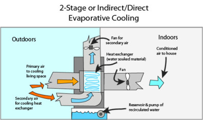
Evaporation Cooling: As the name suggests, this method is based upon natural cooling via evaporation. The bodily process of sweating is the most quintessential example of this process, and the selfsame principle can be extended to serve evaporative coolers. More information can be found HERE.
Here’s how an evaporative air cooler works:
- A pump circulates water from a reservoir to a cooling pad that becomes wet.
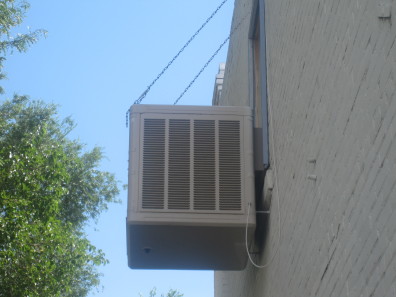
- A fan sits in reverse so that it draws air from outside the unit so that it flows through the wet pad.
- As the air passes through the pad the air is cooled by the natural process of evaporation.
- The cool, fresh air exits the unit to air condition the indoors.
Vapor-Compression Refrigeration: A refrigeration system contains a compressor, condenser, a throttling device, and an evaporator. The system additionally includes a fluid that circuits the closed path of the system (known as the refrigerant) which was favored over water due to its lower boiling point. The refrigeration system may be divided into two pressure zones: a high pressure zone and a low pressure zone. More information can be found HERE.
Here’s how a refrigerator works:
- The compressor causes the refrigerant vapor’s pressure and temperature to increase, thus causing it to push upwards towards the condenser.
- The condenser cools the vapor as it comes into contact with the cooler, room temperature air.
- The refrigerant is now in liquid form at high pressure. As it enters the fridge it absorbs the heat inside and cools the air down.
- The TX valve releases the pressure, causing the refrigerant to cool down where is enters the evaporator.
- The cold liquid goes through the evaporator and turns into a cool gas.
- The refrigerant enters the compressor and the cycle restarts.
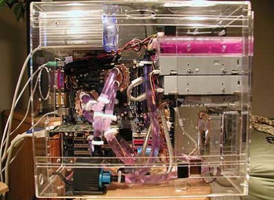
Liquid Nitrogen Cooling: Cooling via liquid nitrogen presents itself as another effective solution. It is commonly used by avid PC gamers to prevent their expensive hardware components from overheating. This process is extremely effective due to the fact that liquid nitrogen functions at extremely low temperatures. This process grants computers the ability to operate at optimum performance levels without posing any threat to the physical components. This picture below shows a PC with an integrated liquid nitrogen cooling system. More information can be found HERE.
Carbon Dioxide Cooling: Instead of using refrigerant or liquid nitrogen, CO2 is yet another option for a refrigeration cycle. CO2 has been used in industrial applications for a while but is recently becoming more universal in commercial and food industries. However, implementing CO2 in a refrigeration system requires some design changes to account for CO2 being more dense than other refrigeration fluids. More information can be found HERE.
Turbo Expander: One idea to conserve power in a refrigeration cycle would be to integrate a turbo expander into the process. The idea behind a turbo expander is that a high pressure gas enters, expands, and leaves at a very low temperature. When the gas expands, it produces work as a byproduct. This work can be fed back into the system as power if we need to.
Joule – Thomson Valve: Also known as a throttling process, this valve expands and cools either a gas or liquid. The valve is insulated so that heat does not escape to the surrounding environment. Throttling is used in refrigerators, pumps, air conditioners and liquefiers. This will be a crucial component in our design if we decide to go with a refrigeration process.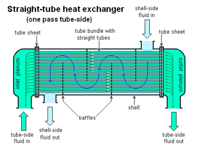
Heat Exchanger: This device allow heat to pass from a liquid/gas to a second liquid/gas without having the two mix. Heat exchangers work by feeding the hot fluid/gas through a set of coils that are inside a larger tube in which a colder liquid/gas flows in the opposite direction. Heat is exchanged from the hotter liquid/gas to the colder. More information on heat exchangers can be found HERE.
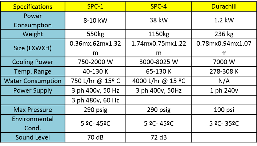
Stirling Cryogenerator (Stirling Cycle): The Stirling cryogenerator uses a Stirling cycle to cool an output fluid with a closed working fluid system. The Stirling Cryogenics SPC-1 unit can accomplish our level of 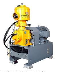 desired cooling, however it is not nearly as efficient or cost effective as we would like. At roughly $200,000 per unit, we think a custom system with a different cycle will suit our needs better.
This thermodynamic cycle was invented by Scottish minister Robert Stirling in 1816 to use mechanical energy to drive a heat pump. This system is a closed regenerative cycle where the working fluid is contained within the system and an internal heat exchanger, named a re-generator, is used to increase the efficiency of this process. Information regarding how this process works can be found HERE. For more on how Stirling Cryogenics applies it to the SPC line of units, visit their website.
Mixed-Refrigerant (MR) Processes: MR processes involve a mixed working fluid to produce a refrigerant with properties which fit the desired task better than standalone fluids. One example comes from the IdealHY projects, which used Nelium (a 75/25% mix of helium and neon) to produce a sliding temperature change during phase change processes. Applying this process in a cascading MR system allowed IdealHY to apply only two Brayton cycles a common compression system in order to cool from ambient temperatures to 130K. Other systems with single refrigerant cycles required repetitive compression and expansion stages, upwards of 15 compressions and 7 expansions, for the same efficiency.
Vortex Tube Cooling: Much like our patent-pending vortex tube system for our final Hydrogen cooling stage, vortex tubes can cool our refrigerants. Vortex tubes work by generating spin in pressurized gasses. The spinning gas travels down the tube to the control valve where some escapes. The rest of the gas spins down the middle of the other vortex back to the other end. In the process it rejects kinetic energy in to the outer vortex and exits the opposite end as cooled gas. See the image bellow: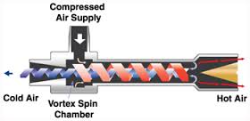 Our refrigerant could be a Nelium gas mixture run through either a Brayton Cycle-based system like Ideal HY. Or we could use cascading vortex tubes with a compressor and an expansion valve. A combination of cycles could even be the best of both worlds.
Standards/Codes: Standards for Piping Design/Material Selection can be found on page 7 HERE.
Challenges
The Pre-cooling team will design a way to cool the hot hydrogen gas down to a temperature that can be used by the vortex tube to be turned into a liquid. This represents some serious design challenges because we are dealing with a huge temperature difference for the hydrogen which requires a large amount of energy to be drawn out from the hydrogen. Not only do we have to remove a large amount of energy from the hydrogen but we also have to efficiently do so at cryogenic temperatures.
Additionally, few systems exist which can efficiently do these things for us. Our cooling system will require customized systems and components to reach our output requirements and achieve our goals.
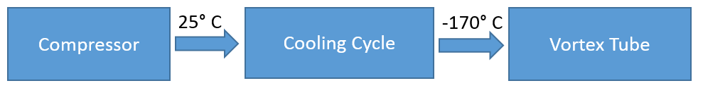
INPUT: Gaseous hydrogen from the compressor at 1400 psi and 25° C.
MUST: Cool hydrogen below -173° C and kept at 1400 psi while maintaining safety standards.
SHOULD: Relatively low cost, cooled to a preferable -203°C, take up minimal space.
OUTPUT: Gaseous hydrogen between -203°C and -173°C to the vortex tube.
Design Specifications
In order to effectively compare the different means of cooling the gaseous hydrogen, we have thought up a list of quality characteristics that represent the ideal cooling process. From there, a table has been created in which we can rank the effectiveness of each of these quality characteristics for each possible design. In the table below, the quality characteristics of the ideal cooling process are listed on the left column. The possible design ideas are listed on the top row. The idea of this table stemmed from well established engineering tables like the House of Quality. The one shown below is simpler so that anybody can see how engineers keep track during the preliminary design process.
Quality Characteristics: There are the 7 quality characteristics that represent the ideal cooling process in our design. These characteristics each play a fundamental role in our design and will all be important to consider for ranking all the design possibilities. Here are the 7 quality characteristics and why they are important for this design:
Safety: This is the most important characteristic because we want everybody to be safe! Engineers have a code of ethics that we abide by and that we promise to always uphold. Everything that we include in our final design will be verified for complying with the appropriate safety standards.
Cooling Efficiency: How well does this process cool the hydrogen. This is a measure of how effective the design is at completing the objective.
Manufacturing Cost: Engineering is all about saving money to make the most efficient design possible. This is ranked as one of the most important characteristics (behind safety) because we want everybody to save money! This means our customers!
Power Usage: Almost every component in this assembly is going to require power. Power costs money, we want to save money. We want everybody to save money. This means that we need to try to find ways in order to keep our power usage low.
Space: This will be important because the container that holds all the components that comprise the hydrogen refueling station is a certain size. Therefore, keeping our subsystem to a reasonable size will ensure that all the systems can easily fit.
Reliability: Does it work everytime? We want our design to work without fail. Ensuring that our cooling system gets the job done every single time is a characteristic of a great design.
Life Cycle: A cooling system that lasts a long time without having to replace is a great cooling system. This just makes it easier for everybody. Having to replace the cooling system more often means more money. We want everybody to save money.
Ease of Maintenance: How easy is it to repair or adjust the cooling system once its been up and running for a while? A cooling system that’s easy to fix will save time and money for everyone involved.

Ranking System: Each cooling process was given a rank of 1-4 for each quality characteristic.
1 – Bad
2 – Good
3 – Great
4 – Ideal
Safety, Cooling Efficiency, and Manufacturing cost were multiplied by 3 since these quality characteristics are the most important. Power Usage, Space, Reliability were multiplied by 2 since they are moderately important. The Life Cycle and the Ease of Maintenance were the least important quality characteristics so their rows were multiplied by 1.
Findings: Based on the rubric we’ve developed to determine the best design, the combination of a refrigeration cycle and a liquid nitrogen bath wins…but not by much.
Preliminary Designs
There are a few paradigms for the process of cooling hydrogen. Namely three that we will consider for our design.
Option 1: Refrigeration Cycle + Liquid Nitrogen Bath
Positives: Less costly
Negatives: Takes up more space
Option 2: Liquid Nitrogen Refrigeration Cycle
Positives: Takes up less space, plenty of sources for components
Negatives: More expensive
Option 3: Carbon Dioxide Refrigeration Cycle
Positives: Great cooling power, more expensive
Negatives: Not as easy to find components as nitrogen
Option 4: Mixed Refrigerant cascading cycle
Positives: High cooling power, common components
Negatives: Larger HE’s means more space needed
Option 5: Cascading Vortex Tubes
Positives: Less space required, efficient process with energy reclamation, no moving parts (except compressor)
Negatives: Intricate process, fully custom
Our Design
 Vapor-Compression Nitrogen Cooling Cycle
This is a basic flowchart of our design for cooling the hydrogen. There are three main flows in our system: A gaseous hydrogen flow, a liquid-vapor nitrogen cycle, and a refrigerant cooling cycle. Basically, hydrogen is the gas we are needing to cool down, we will be using liquid nitrogen to cool it down, and then the nitrogen will be compressed to a working temperature range for our recirculating chiller to cool the nitrogen down. Finally the pressurized nitrogen will drop in pressure to give us the liquid nitrogen to complete the cycle.
The hydrogen coming from the compressor at a temperature of about 298 K needs to be cooled down to a temperature of 77 K. The hydrogen will be pre cooled using a heat exchanger with nitrogen gas before entering the liquid nitrogen bath will then be cooled to 77 K. The hydrogen will then head to the vortex tube for further cooling.
Liquid Nitrogen enters the liquid nitrogen bath at atmospheric temperature, cooling the hydrogen down to 77 K. Once the liquid nitrogen evaporates into a gas it enters a heat exchanger which pre-cools the hydrogen to a lower temperature before it enters the liquid nitrogen bath. Now that we have cool nitrogen gas it gets compressed to heat the gas to a suitable temperature for our chiller to operate at. The hot pressurized nitrogen enters a heat exchanger where a refrigerant cools it down. The cool nitrogen is further cooled and liquefies by having the nitrogen expand adiabatically to atmospheric temperature, from there the cycle is repeated.
The refrigerant cycle simply flows through a heat exchanger; cooling down the nitrogen, then enters a recirculating chiller to be cooled itself.
Components: Here are the specifications of the components that we are interested in for our design
Recirculating Chiller Options:
Economics
Estimated Cost/Size/Power

Estimated Annual Maintenance Cost = $1,000
Present Value of Estimated Maintenance Cost (First 10 years, 6% interest) = $35,000

Moving Forward
The more we’ve found, the more we find we don’t know. To paraphrase Georges St-Pierre, you open a door to learn something and as soon as you open that door you find thousands of doors behind it. This is how far we’ve come while researching cryogenics, nitrogen liquefaction, and the associated subjects. On that note, here’s what we’re working on still:
Cascading Vortex Tubes: A vortex tube can generate temperature decreases of 20°C from the feed gas to the cold output. Using this property in a series of multiple vortex tubes can generate a significant temperature 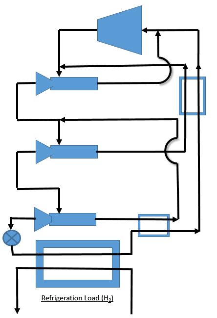 drop. The image on the left demonstrates one possible configuration. It includes a compression cycle followed by three vortex tubes. Each vortex tube is fed by both the feed gas as well as the hot output from the following vortex tube after it has gone through a heat exchange process with the gas leaving the refrigeration portion.
If you start by looking at the primary heat exchanger (Refrigeration Load) you can see it has output refrigerant which then goes through a heat exchanger (HE) with hot output from the third vortex tube (VT3). This ‘hot’ stream from VT3 then merges into the input of VT2. The output of VT2 does the same with the return stream from the Refrigeration Load (RL). The return stream is now warmer than when it left RL-HE but colder than the ‘hot’ stream from VT2.
This process tries to increase efficiency by reapplying the cooling we’ve already generated through a series of temperature differences. The most dramatic difference is between the hydrogen feedstock and the cooled refrigerant after the expansion valve. After this we still have relatively cold refrigerant which can we recycle.
Future
We are excited to have a design for our cooling cycle! A nitrogen vapor-compression refrigeration cycle will definitely satisfy the objectives that we sought to accomplish in the beginning. An estimate for the cost, size, and power usage for each component has been established. The next step will be to finalize the exact values for each of these components and then to construct a working model. Stay tuned for more!