 Left to Right: Qusiy Almukhaini – Muayad Alaraimi – James Crews – Changsong Ding – Michael Wood
Background
The system we have designed thus far consumes power. There is no way around that. Our task on the power team is to find the safest and most efficient solution, not only in terms of energy but also space, for the power demands of the hydrogen liquefying and refining process. The solution that we find in this section will have to provide power for each component of the system that will require power to run.
Paradigms
Power From the Grid (120/240V) with Battery Backup:
One possible way to power our system is to plug it into the grid. This paradigm seems to be the best option since it is cheap and easily set up. Having our system plugged into the grid makes maintenance simple and easily accessible. This paradigm also has the advantage of not being very sensitive to the temperature or quality of air. Victoria can also be connected to a battery internally in case of a power outage. Although the battery won’t be able to power the system entirely, it will be enough to keep the sensors and other safety precautions set up. While this paradigm seems to be the best, it does have its downfalls. A 10 kW battery can cost anywhere from $4,000 to $20,000 which can be expensive for a industrial grade battery. As of 2016, Avista also charges 13.3 cents per kilowatt-hour.
Proton Exchange Membrane:
The second option we thought of to power the system is to use a proton exchange membrane. This option would draw a portion of the pure hydrogen that is being input to our system to power the various components used to store it. This has the advantages of being lightweight and has a good efficiency of about 50-60%. This option also wouldn’t require refueling since hydrogen is already being brought into the system. The few downsides this option has is the cost is high due to the use of platinum. Also, the membrane is sensitive to changes in temperature which could pose a problem depending on where the system is located.
L.E.A.F Generator (Syngas Generator):
Our third paradigm to power the system is to use a L.E.A.F generator. This generator can be run of syngas to produce power at about 10 kilowatts. This would be a viable option since the input of the first system is syngas, and it wouldn’t need to be purified at all. This also has the added benefit of being the lost cost at about $4500. The downsides with this generator is its weight, at about 500 pounds, and the noise it produces.
Decision
Our recommendation for this system is to use power from the grid with a fuel cell and UPS as backup power. The UPS will be used just to provide power while the fuel cell is starting up and in case of emergencies in which the power from the grid would not be available. This is the most cost and space effective method. The fuel cell also can provide power for much longer than the minimum 2 hours required by the NFPA 2.
Progress
Description of the system:
Initial point of contact with the grid could be many things but in this case it is a three, single phase, fused/metered disconnect box rated for 120V per fuse with 30amps. All three fuses will connect to two separate plug ins, one being a three prong connecter rated for 208V/30A with two hot wires and one ground all 10 gage OS (three capacitor) wire and the other being another three prong connector rated for 120V/20A which are all 12 gage OS (three capacitor) wire.
Following the 10 gage OS wire will lead to a single phase 208V/30A, Type 4X disconnect box with a padlock hole in the lever which is outside the container. From this disconnect box, 10 gage THHN wire being lead through sealed conduit piping will connect to the compressor using a NEMA 4X rated head connection.
Following the 12 gage OS wire will lead to a 120V/20A Automatic Transfer Switch (ATS). The ATS will have at least a 30 second timer, green and red light display where green signals if power is being drawn from the grid. When the light is green power will be drawn from the grid and directed to the rest of the system whose description is will follow. If the ATS does not receive power from the grid (red light) for 30 seconds, using 12 gage THHN wire, the ATS will send a signal to a 1kW rated fuel cell controller telling it to activate.
Assuming the timer has reached its limit and the fuel cell has been told to activate the fuel cell will then draw a source of hydrogen to generate DC power required to run the following system. The fuel cell will then run through an inverter to change the variable voltage from the fuel cell from DC to AC/120V. A long side the fuel cell will be a 12V battery that will then go through a separate inverter to alter the 12V to 120V. Both inverters will then connect to a diode bridge which will allow 120V to be pulled from the system at all times. The diode bridge will then be directed back into the ATS. All of the wires are rated THHN, 12 gage wire which is considered fire proof.
Whether the ATS’s light is green or red there will be an output wire which connects to a 120V/20A disconnect switch which will be locked and only used when the system is clear of any possible chance to leaking hydrogen. The disconnect switch will be needed to turn off the power to the system from the fuel cell, battery, and grid power. From the switch the wire is then separated for to five connections by the use of an electrical panel. Then the panel directs the wire to the system which is a light rated for 120V/.5A, two sensors rated for 120V/.25A, and two ventilation fans rated for 120V/.5A. All of the 12 gage, THHN wire at this point will be directed through the system by sealed conduit piping with NEMA 4X head connections.
Accumulative Power consumption for this system is a total of 300W and for 120V/2.45A
System Concerns:
There are many concerns that the group have come across and are as following:
- We have been unable to contact Avista to discover the charge and overall installation of the grid power meter and disconnect box but have been instructed by an Electrical Engineer at facility operations that it should be included in an estimated cost of labor to be 60% of the 40% cost of the parts for the system.
- There is no standard for Grid plug-ins. The plug-ins our group has chosen for the system are based off of the existing connections in the TRFB laboratory. At the future cite location either a panel has to be installed to plug into or the existing panel head must be bought and installed onto the OS cables. Another option is to skip the plug-in paradigm all together and directly wire the cable into the box.
- Another pressing issue is that fuel cells do not have a set Voltage/Amperage output. Their output is based off of the load resistance which cannot be determined without testing the exact load of the system on the fuel cell. This is an issue because Inverters can change the DC voltage to AC voltage and amplify the voltage to the required 120V (+,- 10%) output but require an exact input range from the fuel cell to run the system.
- Also, in terms of the fuel cell, allowing the fuel cell to get the air it needs, to remain at operating temperatures, and to dispose of the of the waste water has not been addressed due to unknown knowledge of it’s placing by the team in charge of this subject.
- Adding and removing possible future components that require power will could alter the needed components: Disconnect box, plug-in connection head/receiver, ATS, Disconnect switch, electrical panel, Inverter for the fuel cell.
Implementation & Economics
- Wires = $100
- THHR 12 and 16 gauge
- Inverter = 2 x $70 = $140
- Converts the power from the UPS from DC to AC
- Fuel Cell = $3000
- Can provide backup power for an extended period of time
- Disconnect Box = $81.71 * 2 = $163.42
- Protects from shorts
- Doesn’t spark
- 120V/20A ATS = TBD
- Can provide power while fuel cell turns on
- 120V/1A Lights = $25 each
- Provide lighting for storage container
- Conduit Piping = TBD (based on length of wires)
- Protects wires from hydrogen in the system. Required by NFPA 2
- Battery = TBD
- Provides power to safety equipment incase of a power outage
- Diode Bridge = TBD
Regarding the economics of this section, seeing as how the costs of several of the more expensive items on the implementations list are unaccounted for, a cost analysis of this would be uninformative and inaccurate so it has not been included yet. once we have found adequate implementations for these areas of the system, the cost analysis will be updated with those selections.
System Power Requirements
Up until this point in the project, we are not totally certain of the cumulative power requirements for the system. The reason for this being that it has not been assembled and tested yet. Once we are able to assemble the system we will have clear and concise numbers on what the power consumption of the system will be.
Compressors
- How much power will the compressor draw
Insulation
- Getting wiring in from outside the container
Connections
- Pipes to direct hydrogen to the fuel cell for backup power
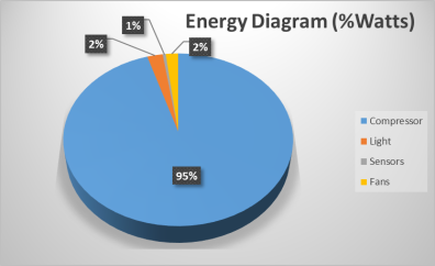
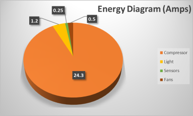
Energy Diagrams:
These two energy diagrams show the relative power consumption in %Watts and Amps of each power consuming component of the system
This diagram demonstrates the flow of power through our system
