The use of a vortex tube in hydrogen liquefaction has never been done before. The vortex tube is one of two distinguishing factors in our fueling station design. The patent protected HYPER vortex tube is more efficient than conventional refrigeration cycles for cooling fluids to temperatures below 75K. An applied catalyst assists the cooling process by converting from para-hydrogen to ortho-hydrogen in an endothermic reaction and ultimately increasing the overall cooling. The use of a vortex tube is essential to increasing the cooling efficiency of the overall system.
Hydrogen Energy States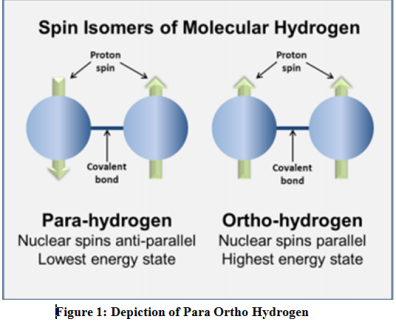
Understanding the properties of the two energy states of hydrogen is key to the performance of our vortex tube. Para-hydrogen and Ortho-hydrogen refer to the rotation of the atoms in the diatomic molecule. The diagram to the right helps illustrate their difference. The catalyst in our vortex tube converts para to ortho hydrogen in an endothermic reaction which helps cool the gaseous hydrogen.
Objectives
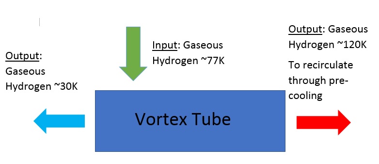
The objective of the vortex tube team is to cool hydrogen gas from around 77K to around 30K while using no moving parts, no energy, and with as little space as possible. A catalyst plated vortex tube will take in hydrogen gas at 77K and output a cold stream at about 30K and a hot stream at about 120K. The hot stream will cycle back up into the pre-cooling cycle while the cold stream will most likely go through another vortex tube and continue on toward storage. A picture below shows the system block diagram and a simple vortex tube.
INPUT:
- H2 gas @77 K, 1400 psi
- 50/50 % Ortho-Para
- 0.15 g/s
MUST:
- Accept H2 from 0.15 g/s,
- Separate hot (Ortho) and cold (Para) H2
- Collect H2 at ~30 K
- Recycle H2 at ~120 K
SHOULD: Liquefy H2 more efficiently than conventional refrigeration cycles
OUTPUT 1:
- Hydrogen gas ~30 K, 400 psi
- 25/75 % Ortho-Para
OUTPUT 2:
- Hydrogen gas ~120 K, 400 psi
- 75/25 % Ortho-Para
Background
There are many changes that can be made to a vortex tube to control its performance. Below is a summary of these changes and how they affect the vortex tube:
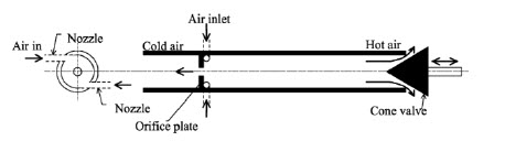
Parallel flow Vs Counter flow:
- Parallel – A parallel flow vortex tube is a vortex tube that has a hole in the throttle valve at the end so the cold stream and the hot stream exit at the same side (picture below)
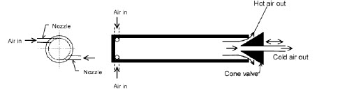
- Counter flow – The hot gas and cold gas exit a counter flow vortex tube on opposite sides. The result is a vortex tube that is more efficient than the parallel flow but can take up more space (picture below).
Further reading for the parrell and counter flow vortex tube can be found on by 1827 of Review of vortex tube phenomena by Smith Eiamsa-arda, Pongjet Promvongeb.
Conical:
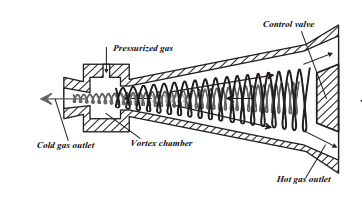
The conical vortex tube uses a conical shape to improve cold separation. The cold exit valve is smaller in diameter than the hot exit valve and the ideal conical angle is around 3 degrees. Conical vortex tubes are ultimately more efficient than a cylindrical vortex tube (Picture below).
Rifled:
Rifling on the inside of the vortex tube works much like it does in a rifle. The rifling along the tube will assist in the vorticity of the gas. The application of rifling may also create a greater endothermic reaction from the catalyst.
Plenum Designs:
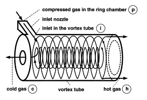
The plenum chamber (VortexTubeOptimizationTheory and Improving Vortex Tube Performance Based On Vortex Generator Design) is a pressurized chamber immediately after the inlet and before the flow enters the tube. After the chamber will be a nozzle with multiple chutes to allow the flow of gas. These chutes are angled so t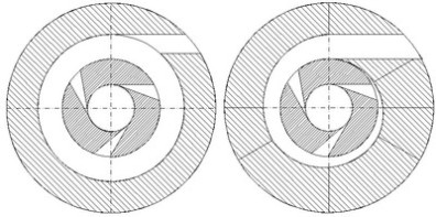 hat the gas enters the tube tangentially generating a vortex in the tube. The use of a plenum chamber and this nozzle make the creation of the vortex much quicker and more effective. To the right there are two examples of plenum chambers and an example of the nozzles. The white ring is where the gas in traveling and the white chutes toward the inner circle represent the nozzles. The number of nozzles and their angles can have a big effect on the creation of the vortex in the tube.
Cascading:
The use of Cascading vortex tubes in series to increase the cooling effect.

Non-adiabatic:
A Non-adiabatic vortex tube tube has no insulation. In this configuration it would be possible to use the tube itself as a section of a heat exchanger.
Variable flow ratio:
Changing the input and output flows allows for optimization of the vortex tube in terms of flow rate.
Design Specification
Based on all of these different design parameters we made a house of quality to quantitatively show how each design compares to each other. Using this, the vortex tube team has come to a conclusion on the optimal design of a vortex tube.
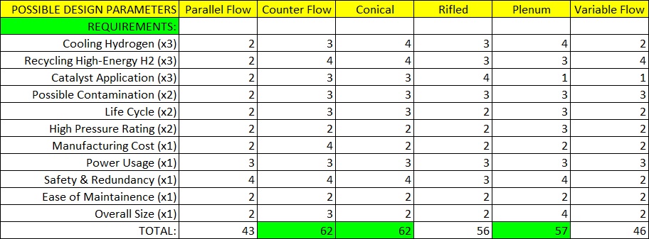
The requirements are weighted based on their importance in the final design. This weight system insures the less important qualities of a design cannot over power the more important qualities in the design thus providing an accurate representation of the best options. Below are listed what our house of quality show to be the best design parameters.
Optimal Vortex Tube Design Parameters
- Conical Tube Shape
- More efficient than a linear tube
- Greater temperature difference between hot and cold
- Plenum Chamber with 6 inlets
- Increases inlets without increasing external piping
- More inlets generates a better vortex
- Counter Flow Outlets
- Greater cold fraction
- Assists in the vorticity of the tube
A CAD model with flow simulation is shown below for a vortex tube with the above characteristics.

Whats Next?
We have identified a gap in the current vortex tube technology base. No vortex tubes on the market are designed for gaseous hydrogen at very low temperatures. Most vortex tubes are also very basic in their design parameters. Now that we have design parameters we will be contacting a local machine shop to build our custom vortex tube.
(Through our research we have realized that there currently is not a commercial vortex tube that perfectly fits our needs. No vortex tubes on the market are designed for gaseous hydrogen at very low temperatures. Most vortex tubes are also very basic in their design. Now that we have optimized our design parameters we will be working with a Washington State University machine shop to create our ideal vortex tube.)
The following steps are part of our planned vortex tube design:
- Building a working CAD model
- Using CAD flow simulation to create the theoretical best dimensions
- Manufacture the vortex tube design created in CAD
- Test the manufactured tube for performance
- Iterate the tube based off of tests
- Manufacture a final vortex tube
Following the above steps will result in the best possible vortex tube to cool hydrogen to near liquid levels.
Engineering Economics
Vortex tube costs:
Each vortex tube will cost approximately $1,000. At an estimated interest rate of 6% we have calculated the future cost of a vortex tube in 10 years.
Estimated cost: $1,000 and 6% interest
Estimated Future Cost = C (F/P, 6%, 10) = $1,000 x 1.7908 = $1,790
Using our previous estimates we can estimate the cost for our three tube sub-system
Estimated system cost: $3,000 at 6% interest
The future cost for three tubes will be $5370
The vortex tube itself has no maintenance cost because of the lack of moving parts. However the catalyst will most likely lose its potency over time so there will be a maintenance cost due to the catalyst. More research is needed to determine the cost.
Depreciation:
Our three vortex tube system will depreciate over time. Below is the estimated book value of our three vortex tube sub-system in ten years.
$3000 (0.967) = $2901
Book Value = 3000 – 2901 = $99