Washington State University
News
Propulsion Team Update
p.charoonsophonsakOur solid propulsion team has been working to create and develop our own solid APCP rocket motor. Specifically, we have been reverse engineering the commercial Cessaroni M1300 motor, as we have modeled the performance of this motor according to our rocket specifications. The APCP motor fits within the competition constraints, is a powerful solid propellant, and is proven as a solid motor by NASA. We also chose the cross symbol as the grain geometry due to the thrust curve and immediate power required to get off the ground initially. We will be ordering our aluminum casing from a commercial site, which will also provide heat shielding and case parts for our motor. We decided to purchase our motor casing commercially due to the fact that creating the propellant is a complex enough task, and creating our own case and case parts would add a drastic amount of unnecessary costs, time, and complexity to our project. We have also put in efforts to locating a test site within the WSU lab spaces and also with the local fire department. In addition, we will be strongly focusing on creating processes and safety during our testing. There has been great progress and work done on our team, as we are trying to overcome one of the greatest innovations for this year’s competition. Here is a breakdown of the progress that we have made.
January: We received our materials for motor manufacturing. This included the ammonium perchlorate, aluminum powder, and iron oxide powder. From there, we went ahead and created our first batch of motors to test. Our goals for the initial tests were to successfully ignite a motor without an explosion. Although we took extra safety precautions, we were still not able to successfully ignite the motor on our first test. This prompted us to go back to the drawing board and re-assess our manufacturing process as this was what we suspected to be the flaw in our motor. By the end of the month, we had created a new batch of motors, modified our manufacturing process, coordinated with the Pullman Fire Department for a test site, and created an updated safety checklist. By the time we tested on January 31st, it was a huge success and we were able to successfully launch all 10 specimens that day. Here are some images of the test site and specimens that day:
Here’s a good picture of the launch site. We used the dirt mound that our team member is standing on in the right side of the picture. This was a good, isolated section that enabled us to be far enough away from the launch.
Here is a simple image of our test stand. It essentially works by inserting an igniter down the circular grain geometry. The ignitor is connected to two alligator clips that lead to our fuse box. The motor is clamped down to a 3D printed mount (the red object) and slid down the centering rods. Once we have equipped ourselves with safety gear, we went a head and ignited the motor.
Here’s a great image of the side profile on our launch set up and our motor once it has been ignited!
February: For this previous month, we went ahead and created a larger scale motor to see the viability of scaling up with our manufacturing process. Our tests were all successful, and we were able to take some learning points away from these tests such as additional safety precautions and further knowledge on grain geometry. Later that month, we also started the process of requesting a data acquisition system to collect data on our motor. The rest of the month was filled with modifications of the data acquisition process and adjustments to our APCP motor composition.
Some of our recent accomplishments include a modified test stand, finalization of our data acquisition process, and the beginning the process of manufacturing out nozzle for more detailed tests.
Aerodynamics Team Update
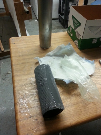
paul.flerchingerAerodynamics has been working on manufacturing the fuselage tube for the past couple of weeks. A mandrel was created to hold the body tube for the layup process. They started out with a single layer of carbon fiber and vacuum bagged it. The result- fantastic layup, no wrinkles, very nice finish.
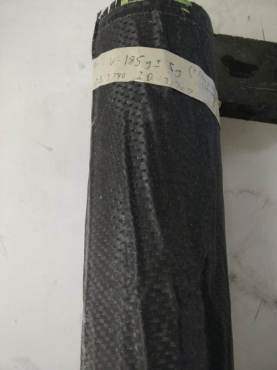
The 2nd and 3rd layups returned less than ideal results unfortunately. 3-4 layers of CF were used for each. Each of the layers had epoxy run through them and pressed out(similar to a prepreg) before being placed on the aluminum tube. This would allow for less movement of each layer when placed onto the tube. The idea was that this would help reducing wrinkles. Each of the layups were placed into a vacuum bag and into the oven to cure. This step seemed to create the most wrinkles. Even though breather was placed around the tube, there were areas that bunched up when the vacuum sucked out all of the air. Thus, they resulted in veiny tubes. Although these can be sanded down, the process reduces the strength of the tube.
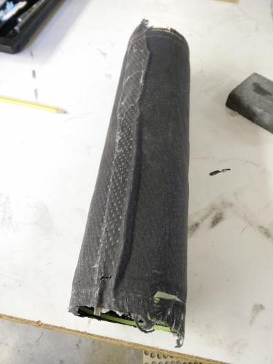
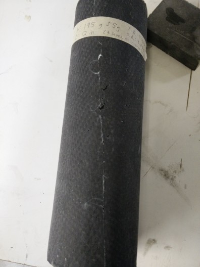
The 4th test was great! The team had a near perfect layup. What changed?! They didn’t use the vacuum bag during the curing process. Instead, after they were done applying epoxy, peel ply was wrapped around the tube and the whole tube went to cure in the oven. The ending result looked spot on. Zero wrinkles and and smooth finish. The thickness with 3 layers was close to .1″.
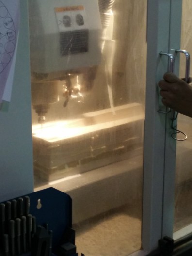
The Von Kármán nose cone was chosen for its low drag and high volume characteristics from subsonic to supersonic. The Von karma shape is a common nosecone profile in rockets of this size. The nosecone mold has been CNC’d and already had a test layup.
Gelcoat was applied 7 times and sanded and smoothed with each added layer. Now, its so smooth that you can practically see your reflection.
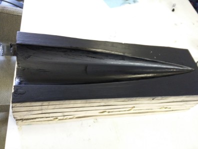
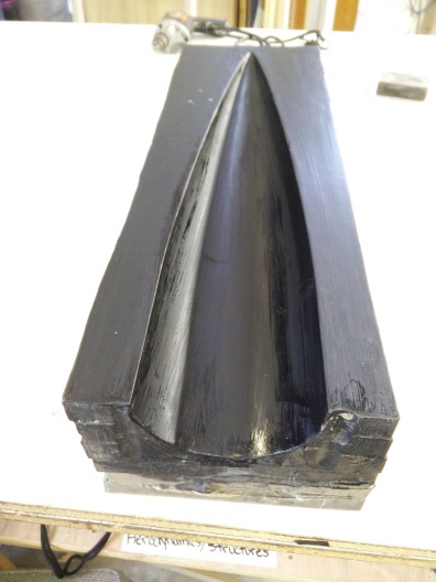
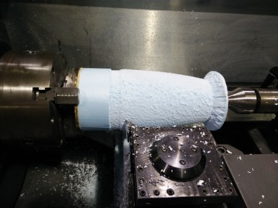
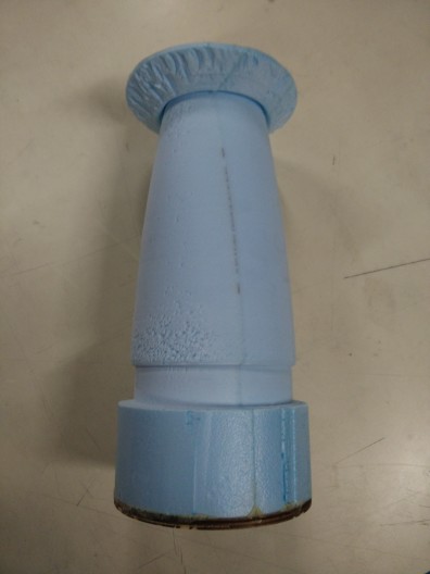
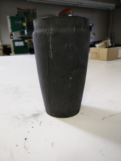
A boat tail is being used to improve the overall aerodynamic shape of the rocket and reduce the amount of drag. The boat tail is also being used to hold the motor casing in the rocket. Initially, the mold started out as turned down foam, was sanded multiple times, filled, and sanded again resulting in a clean smooth surface. The foam plug was covered in layers of fiberglass followed by a carbon fiber sleeve to add strength and match the rest of the rocket.
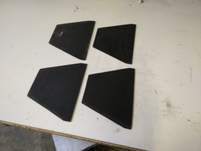
Fin Profile- The hexagonal airfoil was chosen for its low drag performance, durability, and simplicity. Constructed out of BirchPlywood layered with Carbon Fiber.
Electronics Team Update
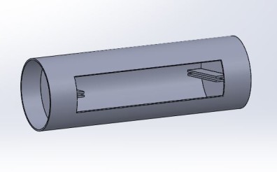
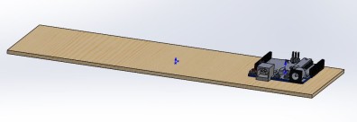
paul.flerchingerElectronics team has been working on the schematic for the internal electronic components consisting of two stratologgers and the ignition system. Their ignition system utilizes a magnetic switch in addition to a physical switch on the outside of the fuselage to easily and safely arm the rocket. The whole system will have a large panel/door for easy access to the electronics while on the ground/launchpad and has removable internal panels to take out the entire electronics bay for more intricate work.
Propulsion Update: Dean
paul.flerchingerWe first build a launch stand using 3D-printed for the launch pad and wooden parts for the stand of the launch. The first two attempts were a success since the rocket was fueled by sugar. The sugar rockets were mildly easy to make since it was basically caramel sugar. Only issues during launch were that the igniter had trouble connecting to the launch box. We eventually came up with the amount of ingredients we needed to make our custom-made ammonium perchlorate rocket fuel. Once we got our ingredients we needed to make our rocket fuel, we began setting up procedures and stir our ingredients into our custom-made rocket fuel.
The third attempt, which was a real test with the custom made ammonium perchlorate fuel, was not a success since the motor exploded but didn’t ignite the rocket fuel. We realized that the rocket fuel may have had air pockets and couldn’t ignite. We developed air lock PVC pipe to prevent air pockets to seep into the rocket fuel, and making several new procedures to mix the ingredients in different ways to get the best results from the rocket fuel once testing begins again. We’re also rebuilding the rocket stand by creating a larger 3d-printed launch stand.
President Encourages STARS Students to join Student Clubs
paul.flerchingerPaul Flerchinger, president of the WSU Aerospace Club, speaks to the STARS students about building rockets and what they can accomplish in a student clubs. Our Aerospace Club is just one of many excellent options available to WSU Students that can provide community service and learning opportunities, a chance to pad your resume with an awesome project, as well as a whole lot of fun!
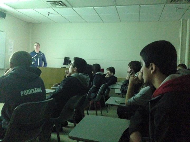
Paul’s motivation:
“I hope to help students get involved with the college no matter what club or event they choose to participate in. Being in a club not only helps you take what you have learned in class and apply it to the project you are working on, but also helps you engage with other people who share a common interest. Good luck out there WSU students- Show others what you can do!”
Media Update
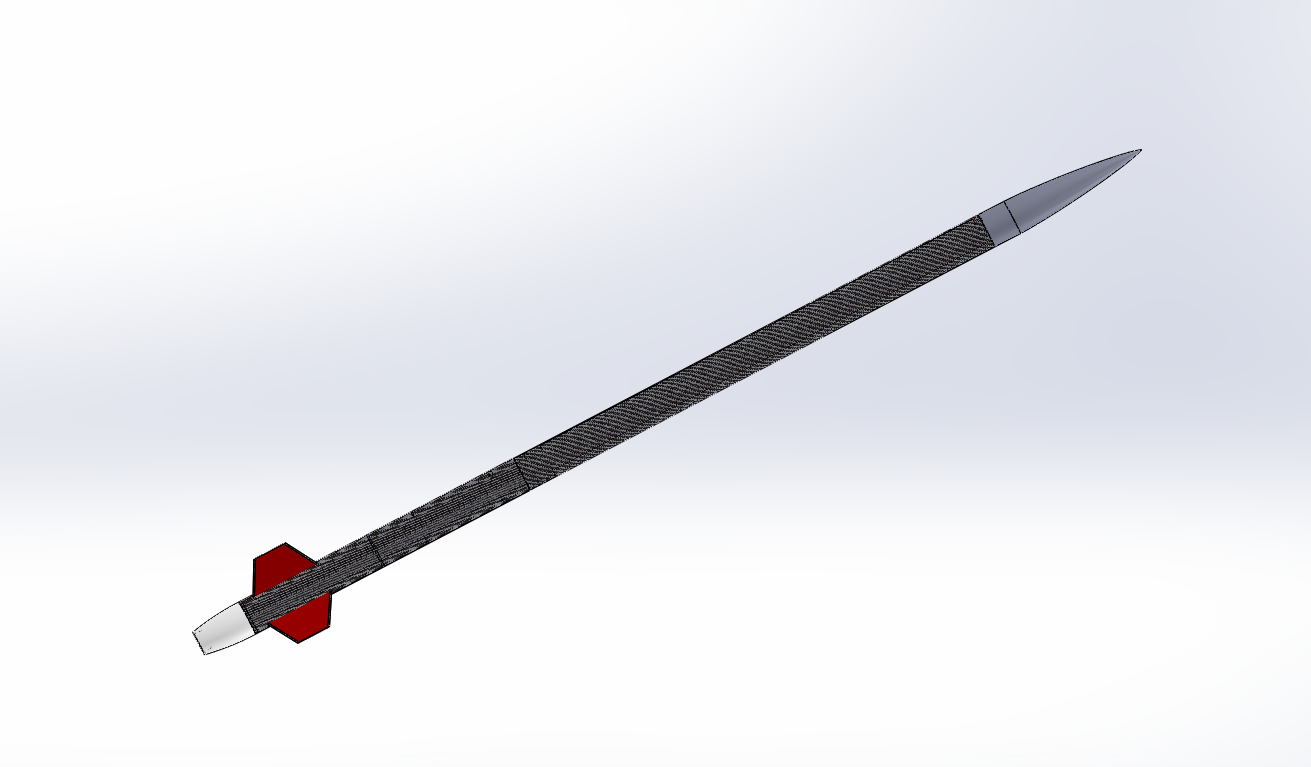
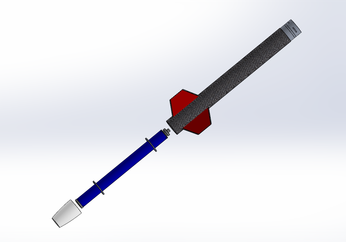
paul.flerchingerFull Rocket View
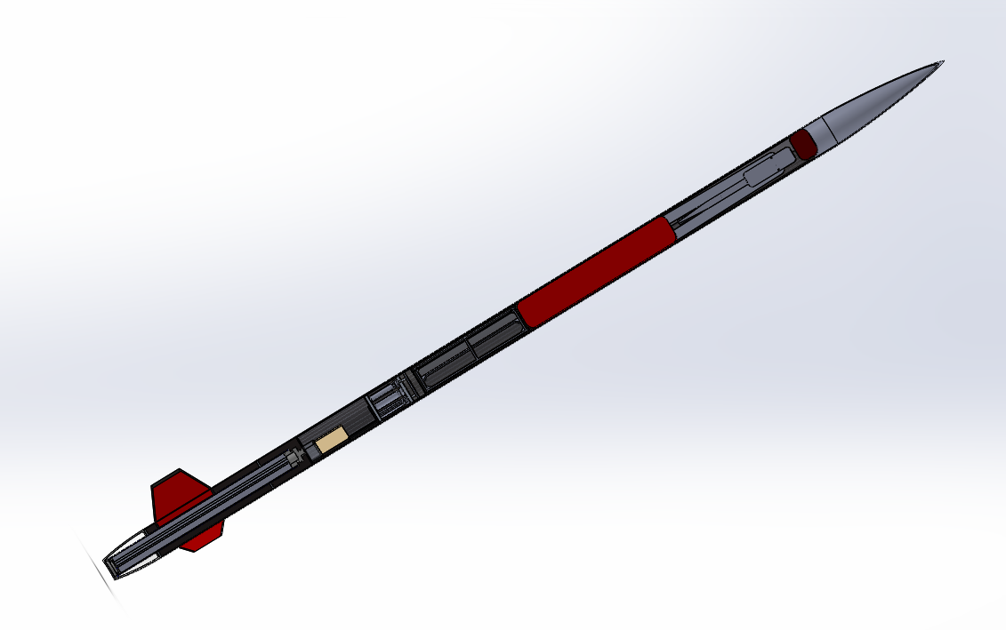
Section View
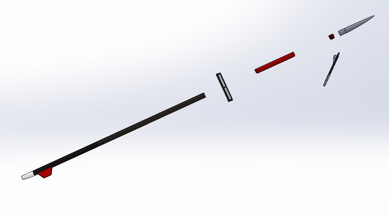
Exploded View of Ground Motor Preparation
Exploded View of Apogee Separation
CougParents Funding
paul.flerchingerThe WSU Aerospace Club was just awarded $1000.00 to be used towards our rocket build from the WSU CougParents Advisory Board! “Final decisions were based on the effect of each program on the WSU Student body, type of program to be funded, need for funding, and available funding.” Congrats WSU Aerospace Club!
Current Rocket Design Specs
paul.flerchingerAerodynamics
Weight: 28lbs
Length:
- O-Give nosecone
- Trapezoidal fin
- Material CF for body
Propulsion
Weight: 5-7
Length: 24”
diameter: 3”
- Ammonium perchlorate and aluminum
- Commercial engine & case nozzle
Recovery
Weight: 15
Length: 36”
- Controllable parachute
Electronics
Weight: 3lbs
Length: 12”
- See Recovery Presentation
Payload
Weight: 10lbs (Glider~2lbs)
Length: 24” tube, 20” wingspan
- Collapsable autonomous Glider
Hybrid Propulsion
- Oxidizer- nitrous oxide
- Nylon and HTPB
Current Preliminary Rocket Designs
paul.flerchingerAerodynamics
- O-Give nosecone
- Trapezoidal fin
- Material CF for body
Propulsion
- Ammonium perchlorate and aluminum
- Commercial engine & case nozzle
Recovery
- Controllable parachute
Electronics
- See Recovery Presentation
Payload
- Collapsable autonomous Glider
Hybrid Propulsion
- Oxidizer- nitrous oxide
- Nylon and HTPB