Student Names: Casey Adam Doan, Shaynese Deas, Yuling Liu
Student Advisors: Jacob Leachman, Collin Merriman
Instructor: Patrick Pedrow
Date Submitted: 12-7-2018
Introduction
Electrical industrial rotorcraft delivery service is no longer pie in the sky. Amazon has recently completed tests on delivery packages using conventional LIPO battery powered drone. But due to the limitation of conventional batteries, almost all rotorcrafts suffer a limited flight time and can only operate for 15 to 45 minutes before the batteries requires to be recharge. Fuel cell and hydrogen fuel has been developed as a long-term alternative solution due to its specific high energy density. A hydrogen powered drones are approximated to have 3-5 times flight duration over regular LIPO battery powered drone in the market. This project is sponsored by Amazon as they already maintain liquid hydrogen storage capabilities at their facilities for their hydrogen powered fuel cell forklift fleets.
Background
A hydrogen fuel cell is a device that can generates electricity by a convert the potential energy of hydrogen into electricity. There are several different types of fuel cell out there in the market, but the most efficient and most popular fuel cell is a Proton Exchange Membrane (PEM) fuel cell. An entire PEM fuel cell system consists of multiple PEM cell in a stack. A fuel cell is consisted of a membrane, 2 sheets of catalyst, and 2 flow field plates. Hydrogen gas is channeled through a field flow plate and then got strip off its electron by the anode sheet. The membrane will only allows the proton of the hydrogen gas to pass through it. The electron must pass through a seperate circuit, which in turn create electricity. On another side, oxygen will come in and helps pull the proton through the membrane. The only bypass product will be water.
Oculus is in possession of a 6 years old HES H-1000 hydrogen PEM fuel cell that was left over from an old project of the Aerospace Club. The original H-1000 fuel cell was utilized and tested to determine the suitability for this application. After over 10 of hydration following a recommended procedure, it still took 3.5h to reach a peak the maximum power generation of 850W. Based on the old report from the team that was working with this fuel cell back in 2014, during peak performance, it had never exceeded 900W. After 2 phone calls with HES, the company that made the H-1000. it is highly unlikely the FC will ever reach 900W again. This posed a serious challenge for team Oculus because the mechanical team from the Aerospace club and ME 416 requested to have a power system that is capable to produce 1500W. Based on this information, team Oculus has advised the client to move on to a newer and more superior fuel cell FCair 1200 from another company named Protonex. Protonex Technology Corporation has agreed to loan the team their new FCair fuel cell. Their fuel cell has a rated of 1200W.
Another problem facing the team, despite having much higher energy density, hydrogen fuel has a much lower power density compared to regular LIPO. As a result, the fuel cell produces lower current than required to power the motors. On average, all eight motors will burst to around 80-90, and sometime would reach 250A during peak power. The dynamic of the fuel cell is just too slow to handle the sudden load change. To overcome this problem, another energy storage will need to be add to the entire system to help with load demand.
Based on this information, Oculus has decided to design and construct a triple hybrid system consist of hydrogen fuel cell, a LIPO battery and a super capacitor. This would allow the drone to become the electric rotorcraft with a triple hybrid power system (figure 1).
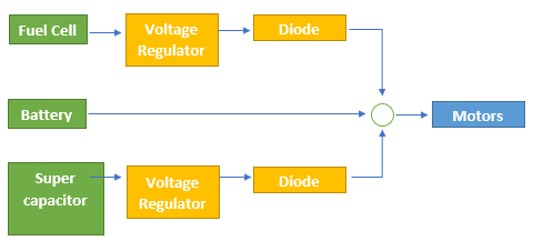 Figure 1. Block diagram of the power system
The development of a hybrid system can utilize the benefit of each system components to meet the load demand, however there is a wide range of configuration options for such endeavor. Figure 1 above show the configuration that Oculus has chosen for the alpha prototype.
Alpha Prototype Description
Oculus has developed a math model (figure 2) on Simulink to model a power flow of the power system and determine the suitability of the 1kV fuel cell for powering the drone. Oculus’s configuration has the fuel cell connects to a unidirectional DC/DC converter, and a bidirectional DC/DC converter for the supercapacitor, where all these power components are connected via a common DC link as seen in figure 1. This configuration allows using the supercapacitor as an energy storage system and SC will have an independent voltage from the entire system. Since SC will have a wide voltage range, it would allow better energy storage. Both the battery and the SC will help the power system to meet the short transient load chances to minimize the load variations on the fuel cell. The design is expected to increase the load efficiency and extend the lifespan of the fuel cell.
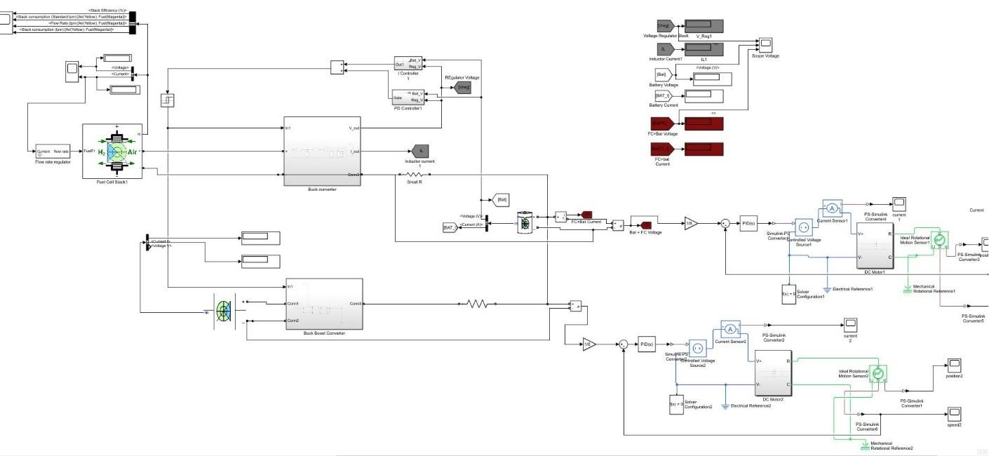
Figure 2. Simulink model of the power system
Unidirectional DC/DC converter:
Because the fuel cell has a much higher voltage than the battery, a buck converter (figure 3) design was chosen as a step-down unidirectional DC/DC converter. Buck converter is a class of switch mode power supply (SMPS) and could provide a very high-power efficiency (90%).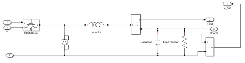
Figure 3 . Buck converter
An IGBT transistor was chosen as a switch for the circuit due to its ability to handle high current, and high lower power. When the switch is on, the power supply will connected to the inductor, the diode become an open circuit. The current flowing through the inductor has an equation (eq1)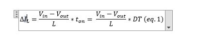
Where ton is the time when the switch is on, T = ton + toff and D is the duty cycle as D = ton/T. When the switch is off, the voltage across the diode will drop to zero, the diode now shunts the connection between the inductor and ground. The current through the inductor decrease with equation 2![]()
This lead to 2 possible operating mode of the buck converter: continuous and discontinuous mode
In the continuous mode (figure 4), when the circuit fall during the off state and rise during the on state. The output voltage can be calculated by using the equation
![]()
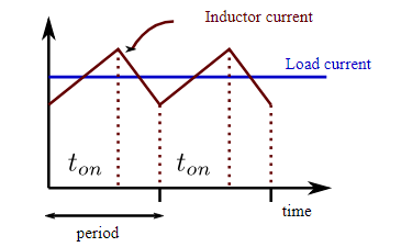 Figure 4. Continuous mode
By control the duty cycle, the reference output voltage can be easily producing with a PID control. However, during a discontinuous mode (figure 5), thing is a bit more complicated.
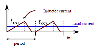 Figure 5. Discontinuous mode
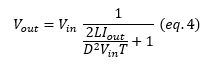
During the discontinuous mode, it is quite common for a DC/DC converter to have its inductor current falls to zero. Inductor current will not persistent enough and will fall to zero before completing the cycle. When the peak inductor current become less than the DC component, the diode will turn on when the switch is off. However, if the peak of the inductor current is bigger than the DC component, the current will fall the zero while the diode is conducting. This will make the diode to stop conducting and the inductor current will remain zero until the switch is back on again. This condition often happens when the during light-load condition, such as moment before lift-off. The equation for Vout is shown in equation 4.
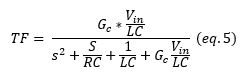
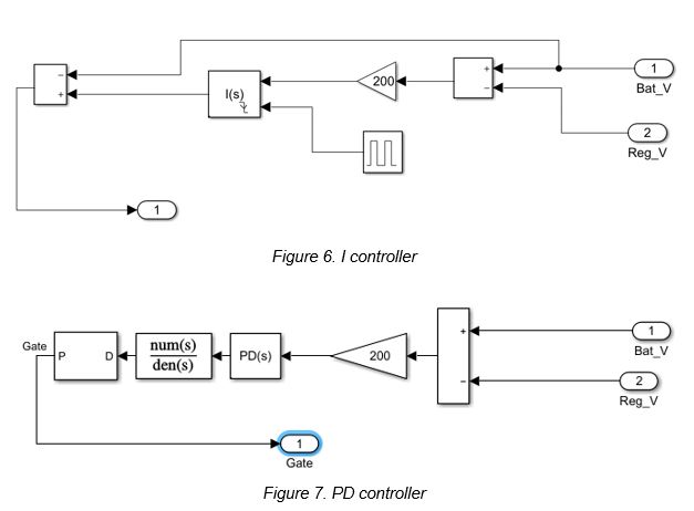
To control the frequency and duty cycle of the buck converter, Oculus has designed a simple PID control (figure 6 and 7). The PID will monitor the overall voltage across all three power components and automatic regulate the frequency to maintain and stable voltage level across the system, prevent damage to the fuel cell and the battery. The transfer function of the buck converter controller was calculated and used to assist the PID
1.2 Bidirectional DC/DC converter:
To improve the power efficiency of the drone’s power system, Oculus theorized that the addition of a supercapacitor in parallel with the lipo-battery would reduce the amount of power the motors drain from the battery. The main function of a capacitor is to store electrical energy and then when necessary, discharge the energy into to the circuit. A supercapacitor is a high-capacity capacitor, and therefore, stores roughly 10 to 100 times more energy per unit volume or mass than the typical electrolytic capacitors. The supercapacitor will accumulate the output energy from the lipo-battery and store it until the system communicates to the supercapacitor to discharge the energy.
To maintain the flow of energy being stored and discharged from the supercapacitor Oculus decided to create a buck-boost converter to act as a switch for the supercapacitor to the battery. A buck-boost converter is a bidirectional dc to dc converter. A bidirectional dc to dc converter allows the flow of power to go in both directions, which means the circuit can feed power to the load and the load can feed the power back to the source. In Oculus’ model, the source would be the lipo-battery and the supercapacitor and motors would be the loads.
The buck-boost converter consists of a MOSFET, an inductor, a diode, a capacitor and a resistor. MOSFETs are metal-oxide-semiconductor field-effect transistors whose voltage determines the conductivity of a device. The ability to change conductivity with the amount of applied voltage can be used to amplify or switch electronic signals. The inductor stores energy from the input supply and discharges energy to the capacitor. The diode is a blocking diode that prevents current from flowing into the right-hand side of the circuit, and therefore allows all current to flow through the inductor. The capacitor stores and discharges energy for the load of the circuit. The resistor represents the resistance of the load and receives energy from the capacitor when necessary.
On-state and Off-state
The principle operation of the buck-boost converter can be expressed using the two operating states of the converter. When the converter is in on-state, the input voltage source is directly connected to the inductor and starts to accumulate energy from the source. While the inductor is accumulating energy, the capacitor is discharging energy to the output load. When the converter is in the off-state, the inductor is connected to the output load and capacitor; and the energy is transferred from the inductor to capacitor and resistor. Figure () shows the on-state and off-state of the buck-boost converter.
Buck-boost converters consists of two different types of modes. The two modes are continuous conduction mode and discontinuous conduction mode.
Continuous Conduction Mode
In the continuous mode, the current through the inductor never goes to zero, and the inductor partially discharges earlier than the switching cycle. The current and voltage waveforms in an ideal buck-boost converter is shown in figure (). When the converter is in on-state, the switch is closed, and the rate of change in the inductor current can be explained with the equation 6.![]()
The Vi represents the input voltage, represents the change in the induction current and L represents the inductor.
At the end of the on-state, there is an increase in the induction current (IL). To determine the amount of change in induction current from the start of the on-state to the end, the equation 7 is used.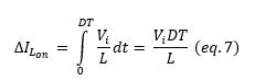
The D represents the duty cycle and the T represents a fraction of the time during which the switch is on. D ranges between 0 when the switch is off and 1 when the switch is on.
When the switch is open it is considered the off-state, and during this state, the inductor current flows through the load. To find the change in induction current for the output, one would need to assume zero voltage drop in the diode and have a large enough capacitor to keep the voltage constant, then the change in induction current can be represented by equation 8.![]()
The variable Vo represents the output voltage of the circuit.
Determining the change in induction current is similar to the one used in the on-state equation. However, there is a variation in the duty cycle and the output voltage is used. The off-state equation for change in induction current is represented by equation 9.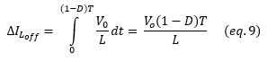
We can see from equation 9, that the duty cycle is delayed in the off-state operation of the circuit. The gain of this model is represented by equation 10.
Discontinuous Conduction Mode
In the discontinuous mode, the current through the inductor goes to zero, and the inductor will completely discharge at the end of the switching cycles. Since the induction current is zero at the beginning of the cycle, it would be considered the maximum current, therefore, equation 11 represents the maximum current in the discontinuous mode.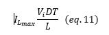
During off-state, the load current (Io) is equal to the average diode current (ID). Therefore,
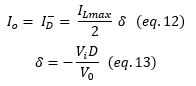
where represents the negative input gain the buck-boost converter has on the duty cycle of the circuit. By replacing ILmax and in equation 12 with equations 11 and 13, one could find the output voltage gain in the discontinuous mode by using simply algebra. Output voltage gain can be calculated using equation 14.
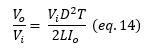
Compared to the continuous conduction mode, the output voltage gain for the discontinuous conduction mode is a little more complicated. The discontinuous operation depends on the duty cycle, the inductor value, the input voltage and the output current.
1.3 DC Motor Modeling
To modeling a DC motor. The rotor and shaft are assumed to be rigid. Here is the physical circuit of a DC motor.
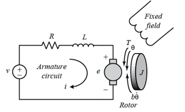
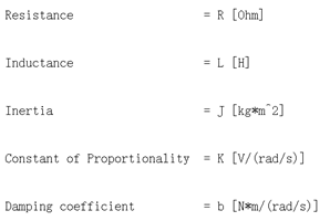
Figure 8 . Physical circuit of a DC motor and its variables
In a DC motor, resistance value R and inductance value L are fixed. For both should be tiny. In DC motor circuit, the value of L can control the system response time. Large L has longer response time. Small L has smaller response time. For a 150W around DC motor, 0.01-Ohm resistor, and 1mH inductor has been considered. J = 0.01. K = 0.01. b = 0.1
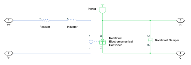 Figure 9a. Simulink model of a DC motor
The blue part is physical model of DC motor, a rotational electromechanical converter is required, which converts electrical energy into mechanical energy in the form of rotational motion. The converter is described with two equations.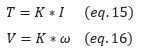
T is torque, V is voltage across the converter, I is the current across the converter, w is angular speed. And K is constant of proportionality. Furthermore, the dc motor has inertia and friction losses, an inertia and a rotational damper block. That all for DC motor, however we need to drive dc motor to rotate.
So, to control the DC motor, a voltage source is needed, which is power enough to maintain the specified voltage, and we serious connect a current sensor to measure current. Each physical network needs a solver configuration and negative voltage input need a ground reference. After DC motor block the electrical energy trans to rotational motion, ideal rotational motion sensor to measure the rotational speed of motor, and port named C is similar with electrical side “V-”, it’s a reference of rotational motion which need to connect to a mechanical rotational reference. The ideal rotational motion sensor is measuring the angular velocity in rad/s (W port), and angular displacement in rad (A port). Then, probe can monitor the motor action.
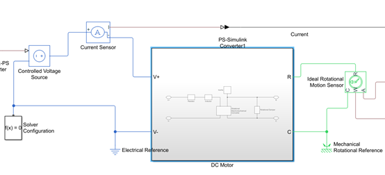
Figure 9b. Simulink model of a DC motor
Before that, physical signal must be converted to math signal. Which allow Simulink probe to connect. For a very basic drone structure, power connected to Electronic speed control (ESC), to maintain dynamic stable of the drone, ESC receives negative feedback speed signal and make the output speed signal stable in steady state region.
In Simulink torque and speed cannot to be plotted simultaneously, hence, another model needed to plot torque. Same as measuring angular speed. An ideal torque sensor needs to be connected, C port as a reference, T is torque in N*m.
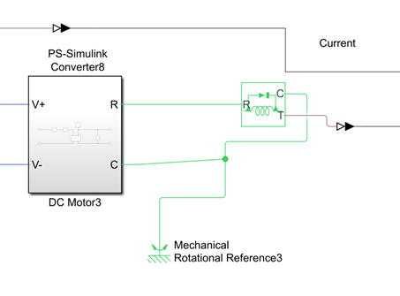
Figure 9c. Simulink model of a DC motor
To find the output mechanical power, P = T*ω, where T is torque in N*m, and ω is angular velocity in rad/s.
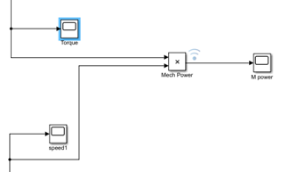
Figure 9d. Simulink model of a DC motor
2. Design Modifications resulting from Alpha Prototype Activities
Oculus’ Alpha Prototype Activities presentation was December 7, 2018, and during the Q and A section of the presentation, a few design concerns and modifications were discussed between team Oculus, the client/mentor, faculty volunteer, professor and student peers. The main concerns that were addressed were the buck converter and supercapacitor circuits.
2.1 Buck Converter
The concern: Collin Merriman, faculty volunteer, brought up the concern for the buck converter and whether or not it was necessary to have the circuit in the design. Merriman mentioned that the motors could take the amount of voltage the fuel cell produces without the circuit, and that having the circuit results in a slight power loss in the overall power system.
Oculus’ response: The main reason Oculus chose a buck converter is to maintain a balance voltage between the fuel cell and the LIPO battery, and not the motor. While many motors could handle 45V input, a 6S LIPO battery won’t be able to handle this much voltage, and most likely will explode due to voltage imbalance. A buck converter allows Oculus to step down the voltage output of the fuel cell with very high efficiency, and also help amplify the current output of the fuel cell. Another reason for the buck converter was to in the efforts to protect the fuel cell from current feedback from the rest of the power system connections. When Oculus first received the H-1000 fuel cell, they thought that was the only fuel cell that they could work with, so a protection plan was implemented. The combination of the concern of the faculty volunteer and the response of the team, lead to the overall consensus that Oculus would look into some alternative ways of protecting the fuel cell from current feedback, but to also reduce the power loss that is created by the buck converter.
Modification: Due to limited amount of information, Oculus had made some assumption around the early design. In October, Oculus received news from Dr Leachman that Protonex and Amazon has agreed to loan 1 of their fuel cells to the team. Protonex currently has 2 fuel cells in production, Fcair1200 (1200W) and Fcair600 (600 W). Based on this information and the expected power requirement, It was a safe assumption that Oculus would receive the FCair1200. Since FCair1200 produces 45V and a 6S LIPO are rated at 25V, a buck converter is a necessary component.
One of the modification Oculus plans to do is to add another 6S LIPO in series together. This should allow the voltage to be balance between the system without using a buck converter. However a 6S LIPO battery weight roughly 1.2kg and any extra weight will require extra power.
But just recently, Dr Leachman and Oculus learned that protonex’s system includes 2 FCair600 in parallel. This piece of information is crucial for Oculus’s next design phase. The combination of 2 FCair600 together will produce a lower output voltage that might match the 6S LIPO while still maintain the power output of 1200W. This allows Oculus to replace the entire buck converter with just a simple diode. This configuration also allows the team to cut the weight of the entire system down. The Fcair1200 is weight at 4.0kg, while the FCair600 is only weight at 1.8kg. So even with 2 FCair600 together, it is still 400 gram less than a single FCair1200. However this also run into another problem. Both version of the FCair fuel cell has the same hydrogen consumption rate at 63g/kWh. By having 2 fuel cells, and only one hydrogen tank available, this might cut the flight duration in half due to the flow rate of hydrogen is now doubling to supply enough hydrogen for both fuel cell.
Due to this information, Oculus is planning to setup a meeting with Dr Leachman, and Dr Merriman for further advice.
2.2 Supercapacitor
The concern: Colin Merriman mentioned that his team and him have tried using a supercapacitor in a power system before, and that it reduced the flight duration in the application of the drone. Merriman suggest finding an alternative for the supercapacitor circuit, or trying to find a way to make it more efficient. Merriman also had a concern in the method in which the battery, fuel cell and the supercapacitor are being switched on/off to alternate the source of the power system to match the necessary power requirements of the motors.
Oculus’ response: The main reason Oculus chose to involve a supercapacitor in the overall power system circuit, was to see if it will improve the efficiency of the power system. According to the Simulink simulation, the addition of the supercapacitor circuit improved the system by reducing the amount of current each motor absorbs from the source. Another benefit the supercapacitor provides is a fail safe for the power system. The supercapacitor acts as a rechargeable battery that can discharge energy at a fast rate for a very short amount of time. It can provide enough power to land the drone safely in the event of an emergency.
Modification: The supercapacitor circuit involves a buck-boost converter. The buck-boost acts as power switch between the supercapacitor and the rest of the power system. Oculus understands that there could be an issue with using a power switching method and using a supercapacitor. However, they plan to modify the converter to make it more efficient, using other topologies of the buck-boost converter. Oculus is considering using the flyback power converter. The flyback topology is that of a buck-boost converter, however, uses a transformer as the storage inductor. Second semester will involve further research on the advantages and disadvantages switching to a flyback converter, advantages and disadvantages of the switching method, and finding ways to make the power system more efficient in terms of desired output.
3. Discussion
Despite misidentify the scope of the project early on the of the development, the ideas found during the waterfall activities has proved itself to be suitable for the alpha prototype. The ideas of building a Simulink model of a triple hybrid power system between a fuel cell, a battery and a supercapacitor have proven to be effective in provide enough power for the drone, and increase the efficiency. By using the agile design concept of failing fast, Oculus has came up with a variety of concepts, and quickly found the most viable design (figure 3). The designs discussed during the design sprint were then evaluated using waterfall methods including a concept screening matrix to help the team choose the best concept.
The alpha prototype shows that the team is currently on schedule despite early setback. However, there are still a lot of work to be done by team Oculus. By spring 2019, Oculus will need to focus on building a testbench, physical power system and integration with the drone frame.
4. Future Iterative Design Goals and Activities Planned for EE416
There are a lot of work still need to be done for next semester. After the demo on December 7, it is clearly shown that despite the math model of the power system will work, Oculus will face a lot of problem with the physical application. This forced the team to push up the time schedule for next spring, so that Oculus will have more time to work on the physical circuit.
Oculus is expected to finish the Simulink model by mid January. Other configuration will be test on the figure the viability. Over the winter break, Oculus will continue to work on developing a model for AC motor circuit and a DC/AC converter to support the AC motor. This would allows a more flexible model for the drone,. Oculus has also spending sometime talking to the FIZ, and the power lab for advice on a using a testbench. Due to high voltage and high current, Oculus will have to build an entirely new techbench that could handle the amount of power, currently the EECS school doesn’t have anything that could remotely withstand the amount of current.
Oculus will also be working together with Dr Merriman to figure out the best switching method for the power system.