Overview
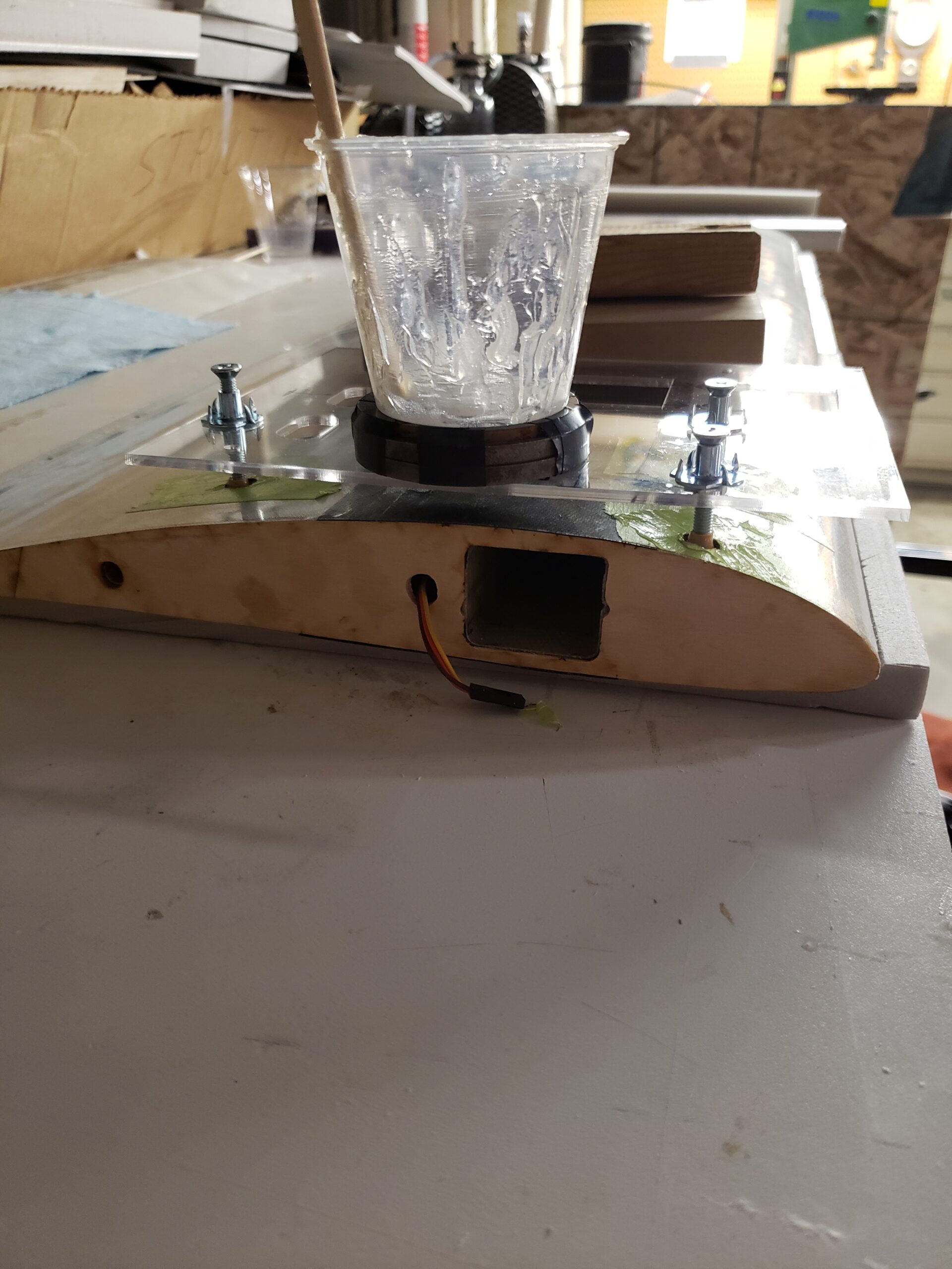
The goal of this cargo plane is to lift a rocket weighing up to 10 lbs to 400ft. This project is for learning composite construction techniques and general model aircraft skills. Given the effort involved in making such a large plane, we decided that we wanted it to have a modular mounting system so that it could be used to lift more than just rockets. A modular mounting system would allow us to build customized mounts for items like a camera gimbal or a smaller deployable plane.
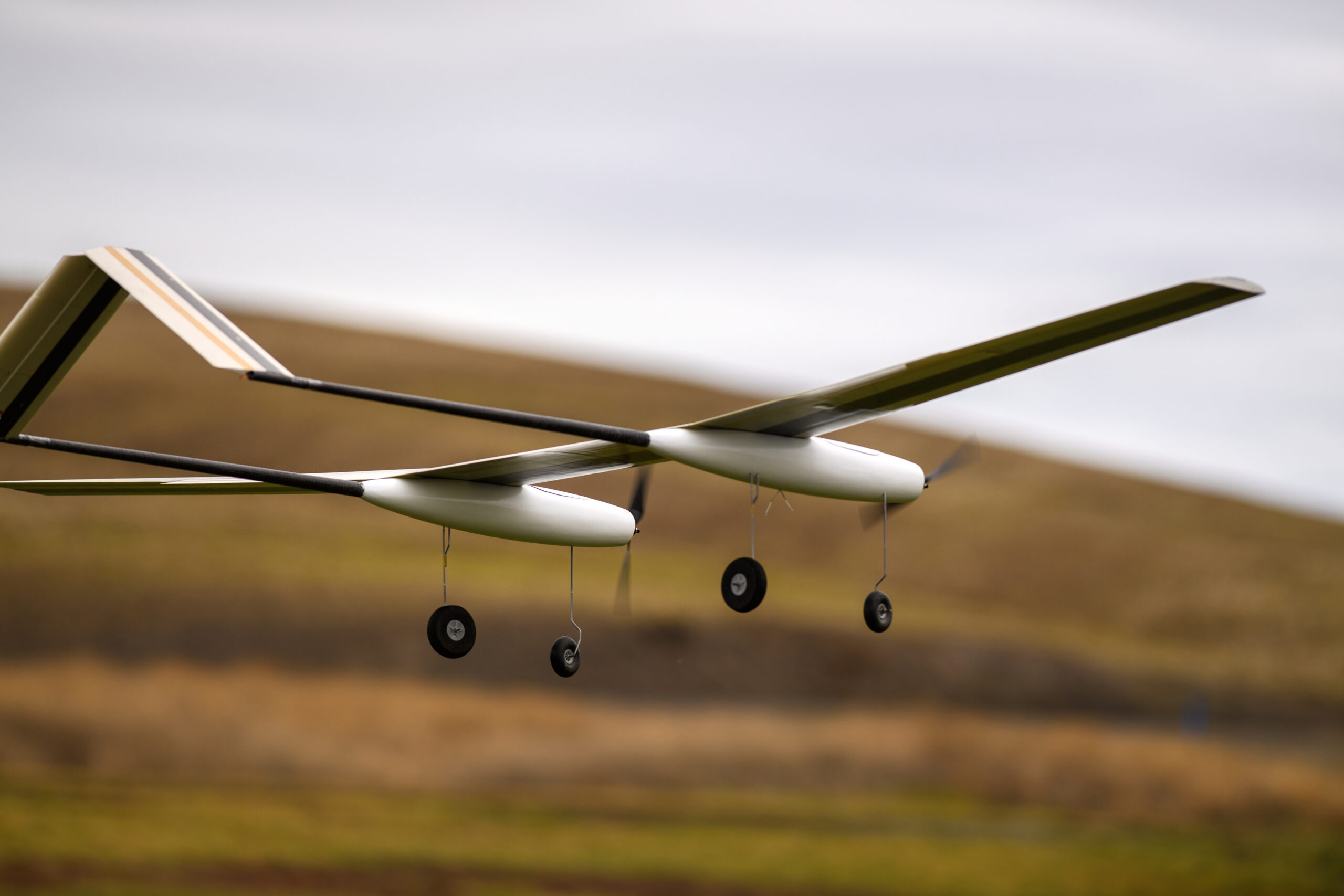
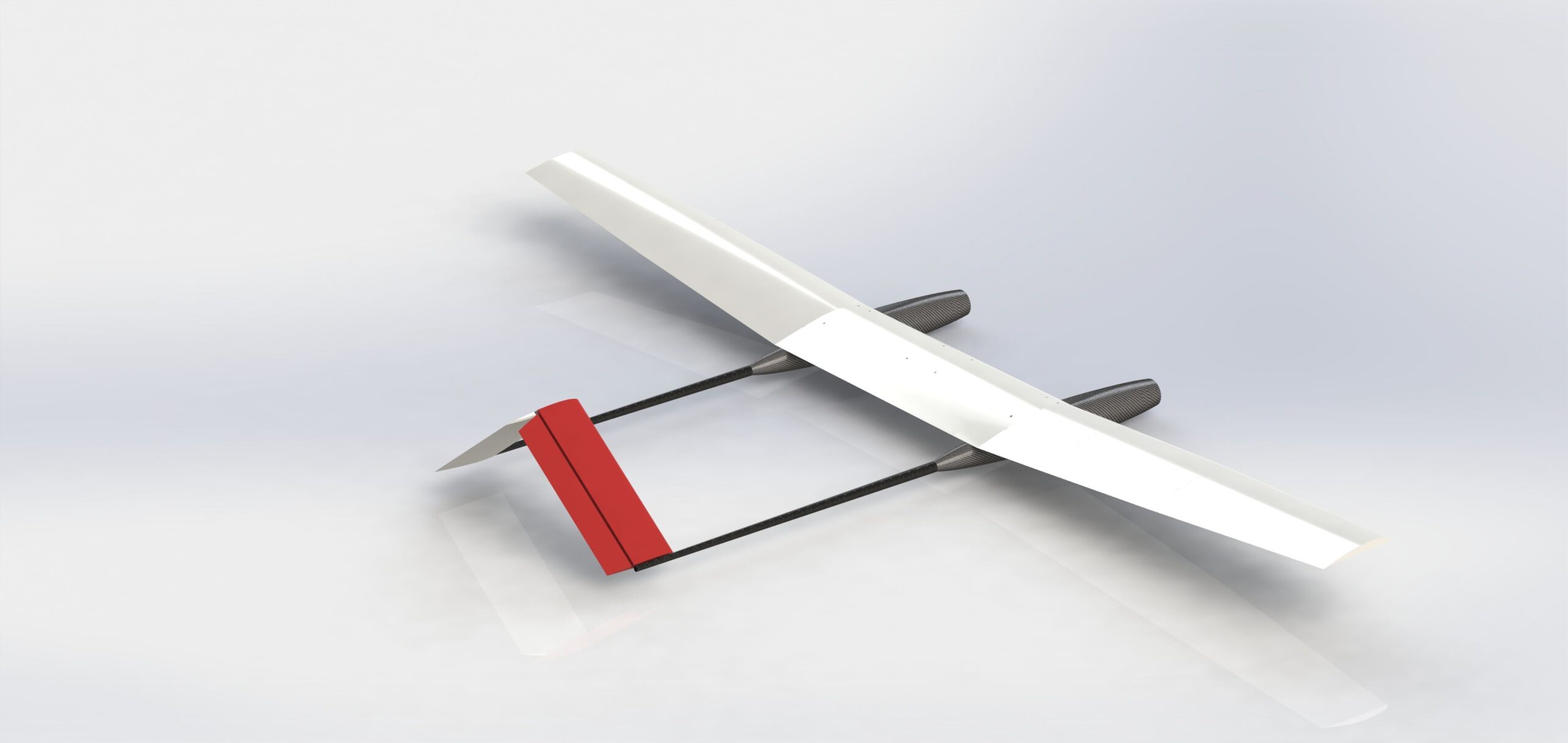
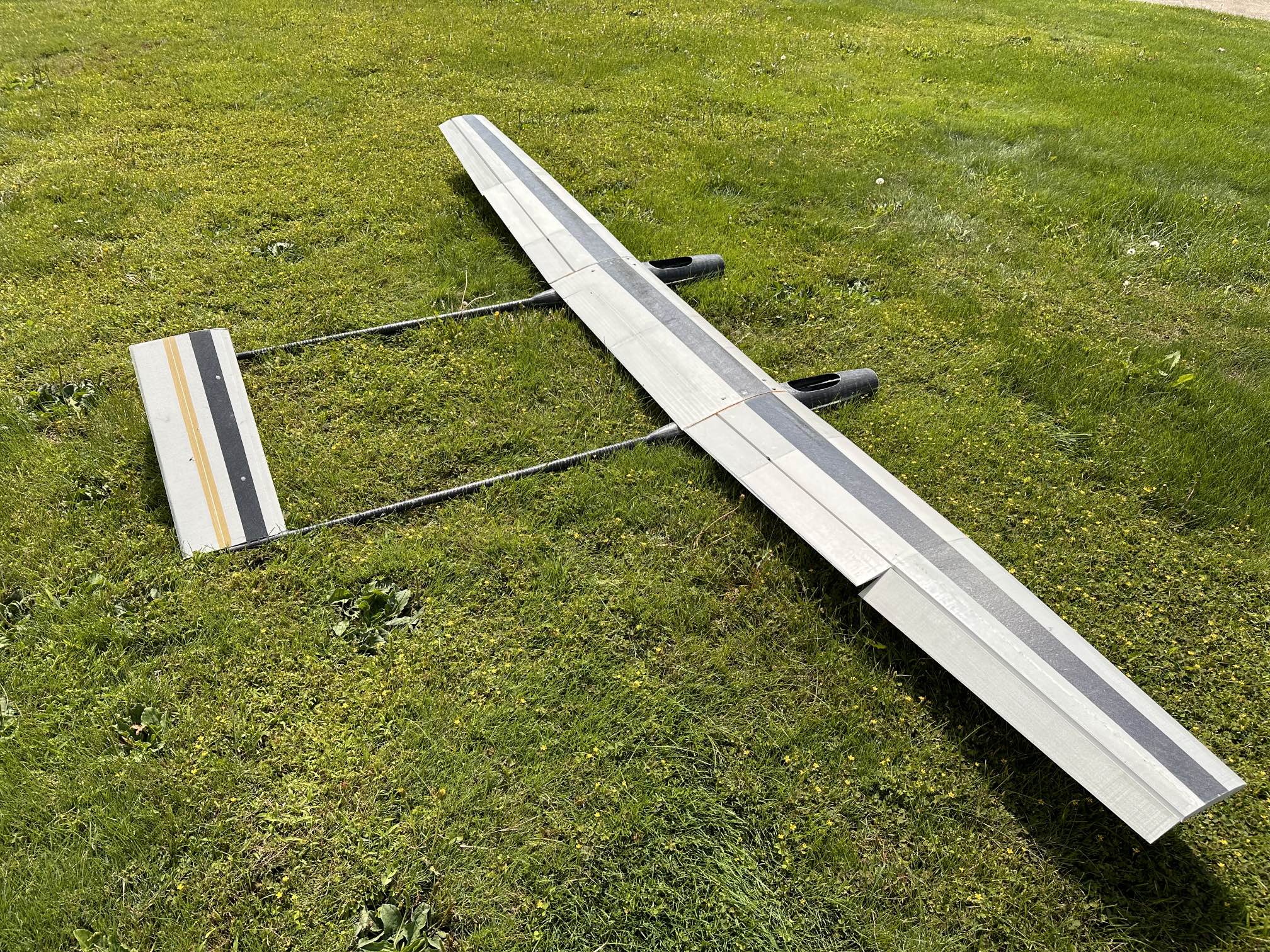
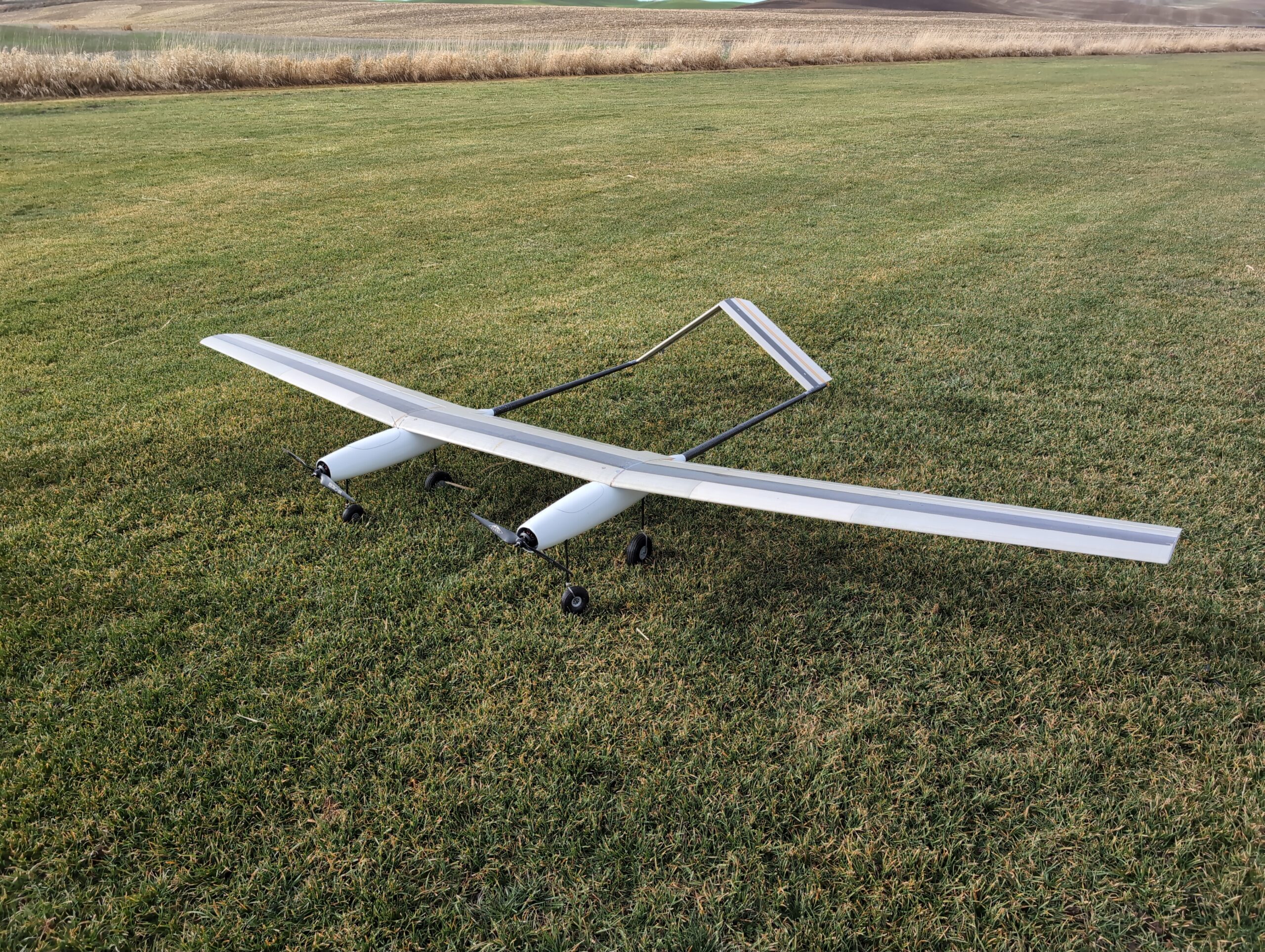
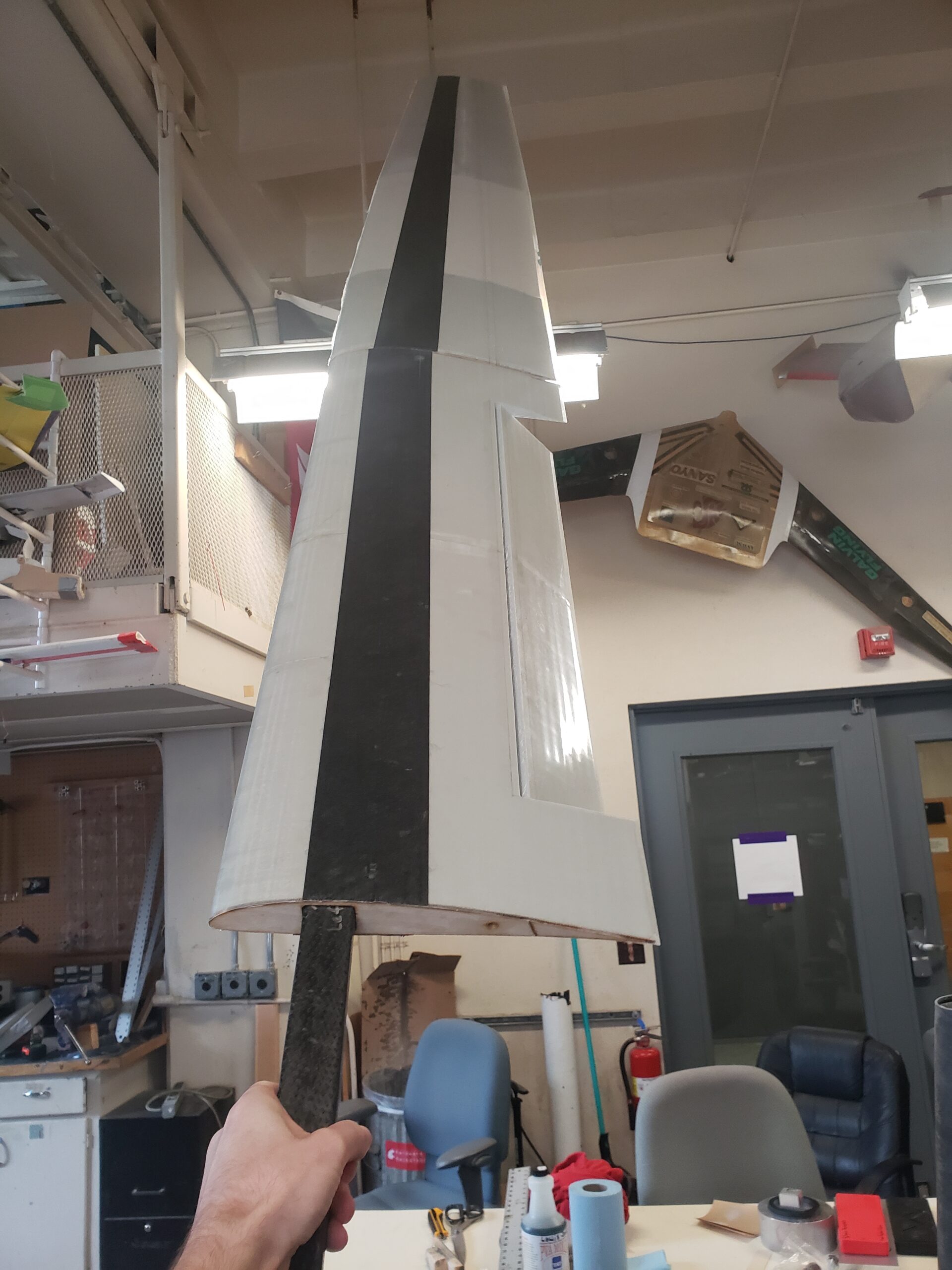
We have opted to use a duel fuselage configuration with the cargo mounted under the center of the wing. This makes for a lightweight plane capable of carrying awkwardly shaped cargo. The tail is an inverted V-tail which reduces the required strength of the booms since they are coupled together and allows us to use just two servos for tail control surfaces.
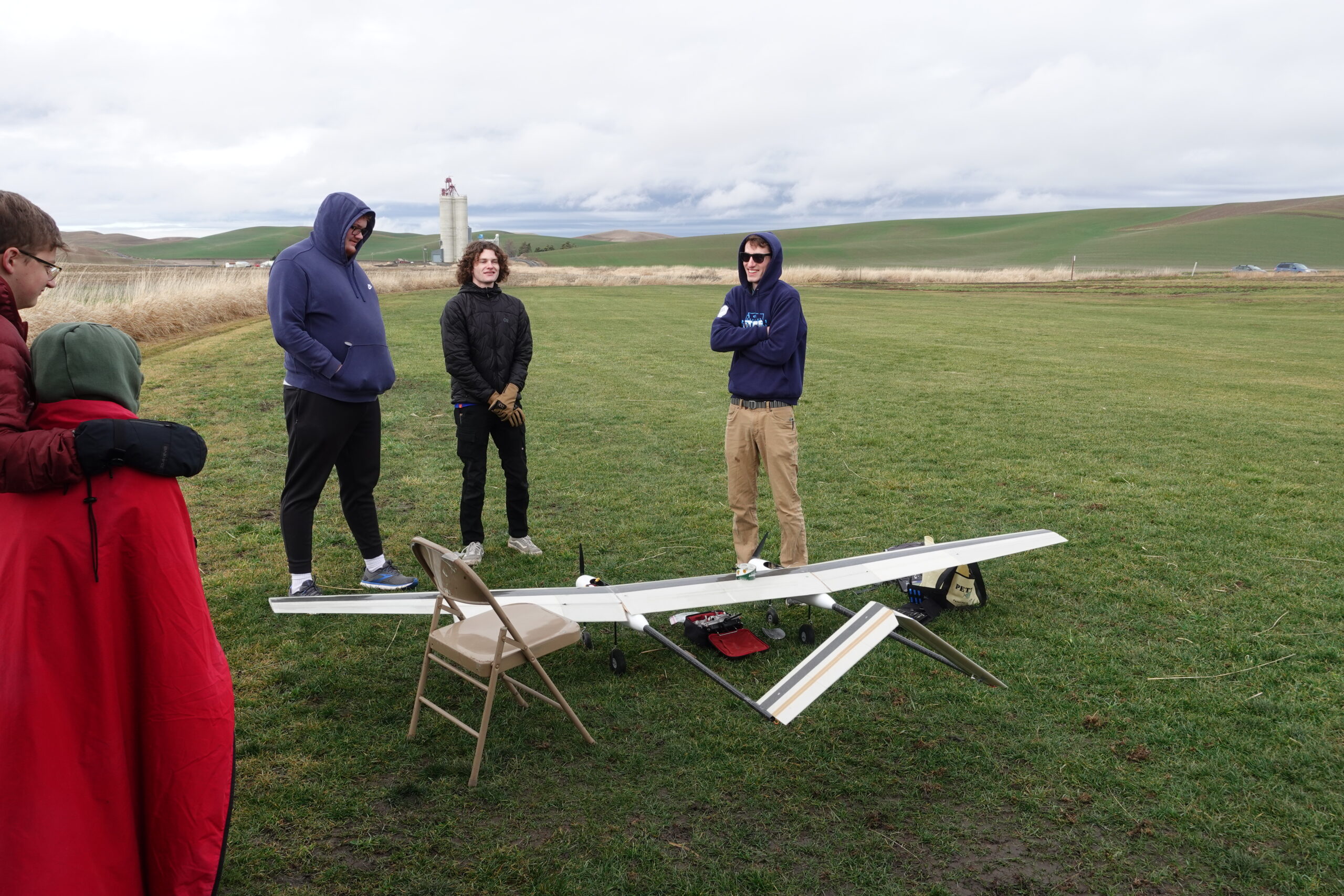
The design for this plane began in the first few months of the fall 2022 semester. Construction of the wing began later that semester and by the end of the spring 2023 semester, we completed the wing, tail, and boom. The fuselages were molded during the last week of the 2023 summer. After getting distracted on design work for a new solar plane project we finally completed the assembly and electronics setup by the end of the fall 2023 semester. A short maiden flight took place on January 27th, 2024. It flew well but a combination of minor landing gear failure and poor weather led to the first month of its service consisting of only short flights in both distance and time in the air. After redesigning the landing gear we were able to fly the plane for approximately 20 minutes on February 3rd. Since then we have flown the plane many more times. In cooperation with fellow WSU club, Cougs in Space, we are preparing for a drop test of their cube sat and its accompanying parachute.
The plane has performed quite well to date. In flight, it exhibits some characteristics of a glider such as long flight times and excellent glide angle. This is to be expected from its high aspect ratio wing and relatively minimal fuselage profile. It is very stable in flight and has no adverse tendencies such as tipstalling. This combined with its high thrust-to-weight ratio will make it perfect for lifting cargo of a wide range of weights. The final weight of the plane without cargo is just over 14 pounds.
Design
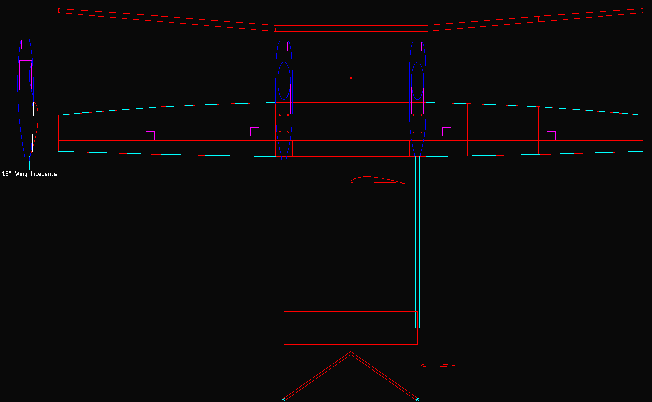
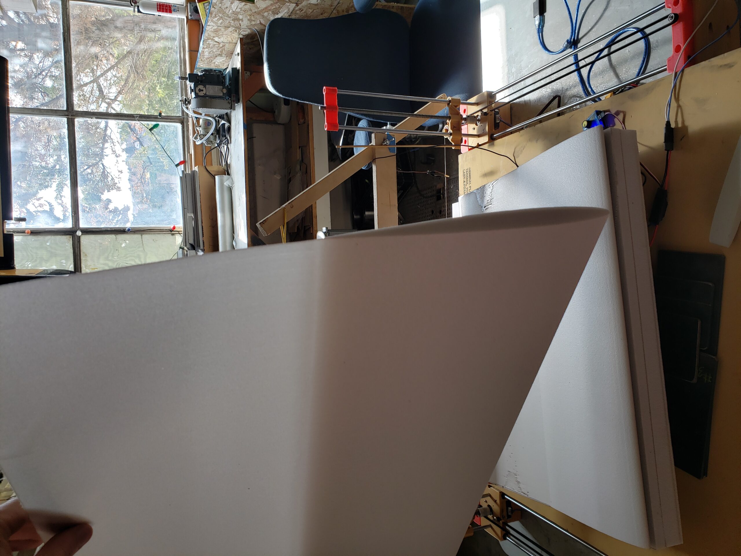
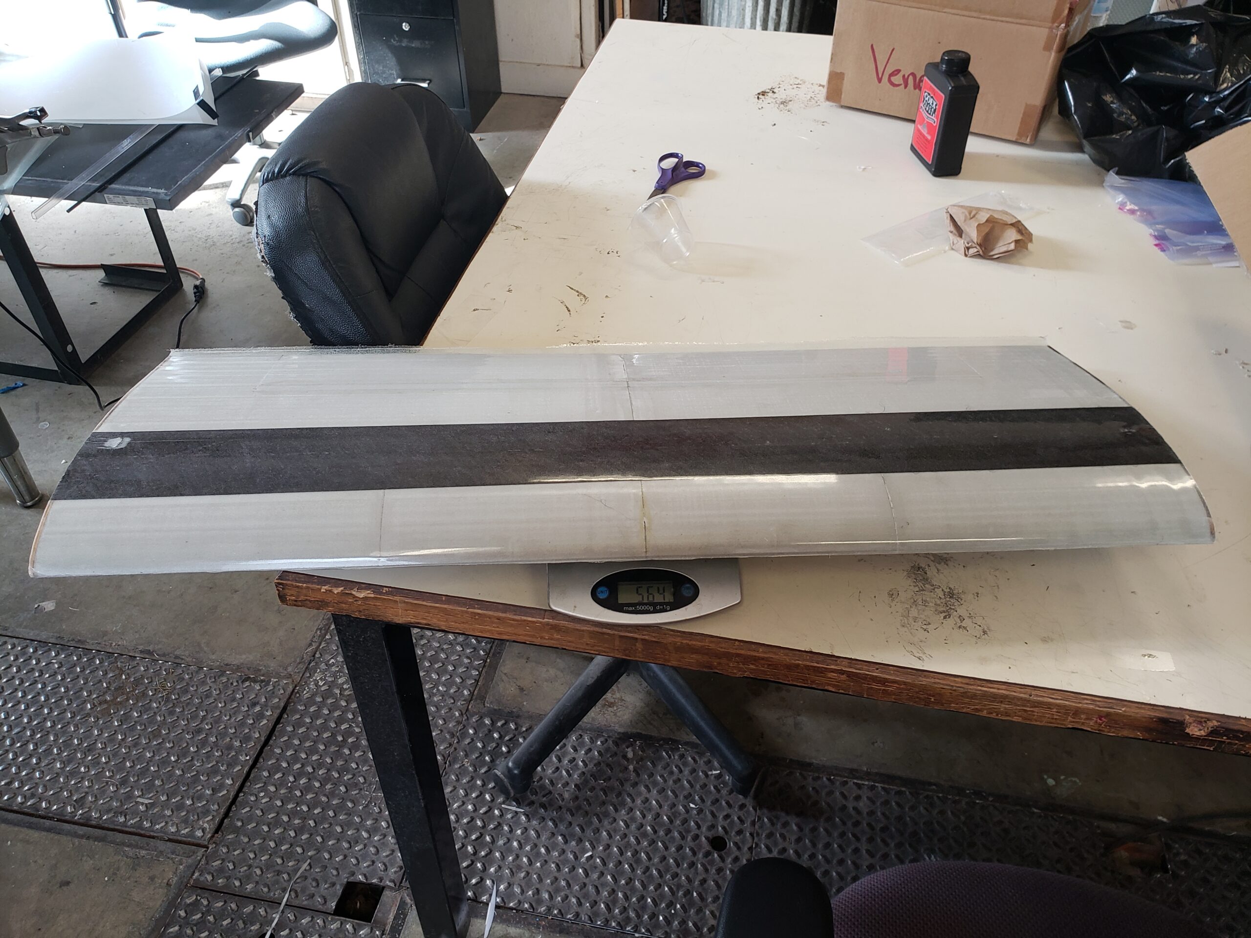
The wingspan is just shy of 12 feet at 140 inches with a root chord of 13 inches and a tip cord of 8.7 inches. The resulting aspect ratio of 12 makes for an unconventionally light wing for a cargo plane. Prior to servo installation, the wing weighed 4.41 pounds. Basic sizing calculations provide confidence that this plane will have no issue lifting 10 lbs of cargo. Using vacuum-bagged composite foam core construction we estimated 15 pounds all up weight without cargo.
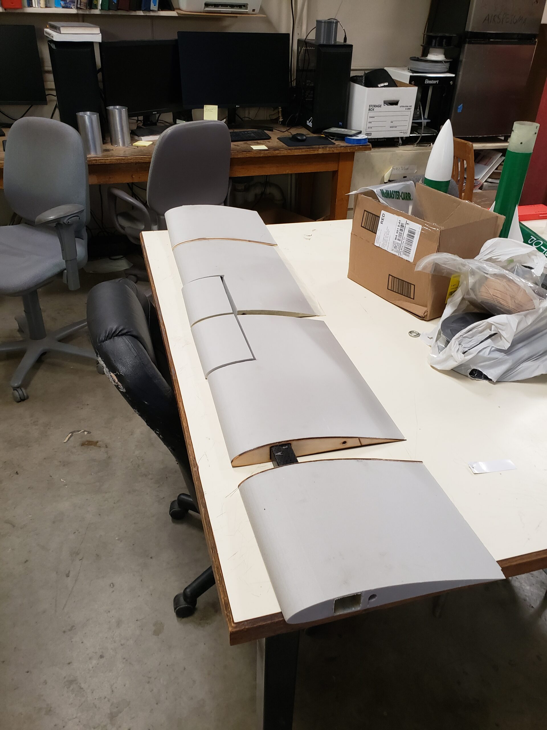
Four airfoils were developed using the help of XFLR5 for this specific application. The entire trailing edge of the wing is split into two ailerons, two flaperons, and one flap in the center. This has the added benefit of allowing the wing camber to be adjusted during flight for a more optimal glide ratio or increased lift for takeoff.
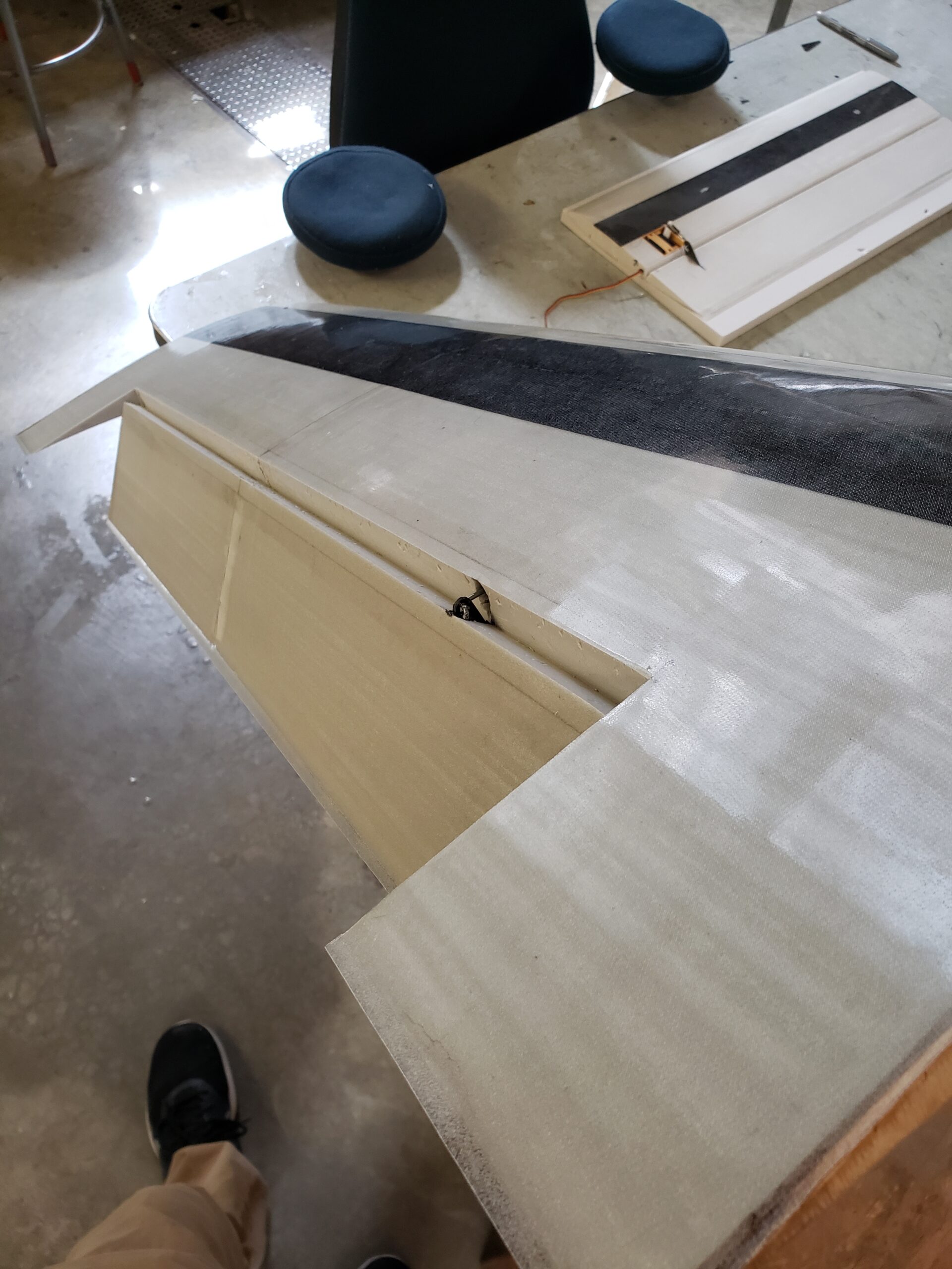
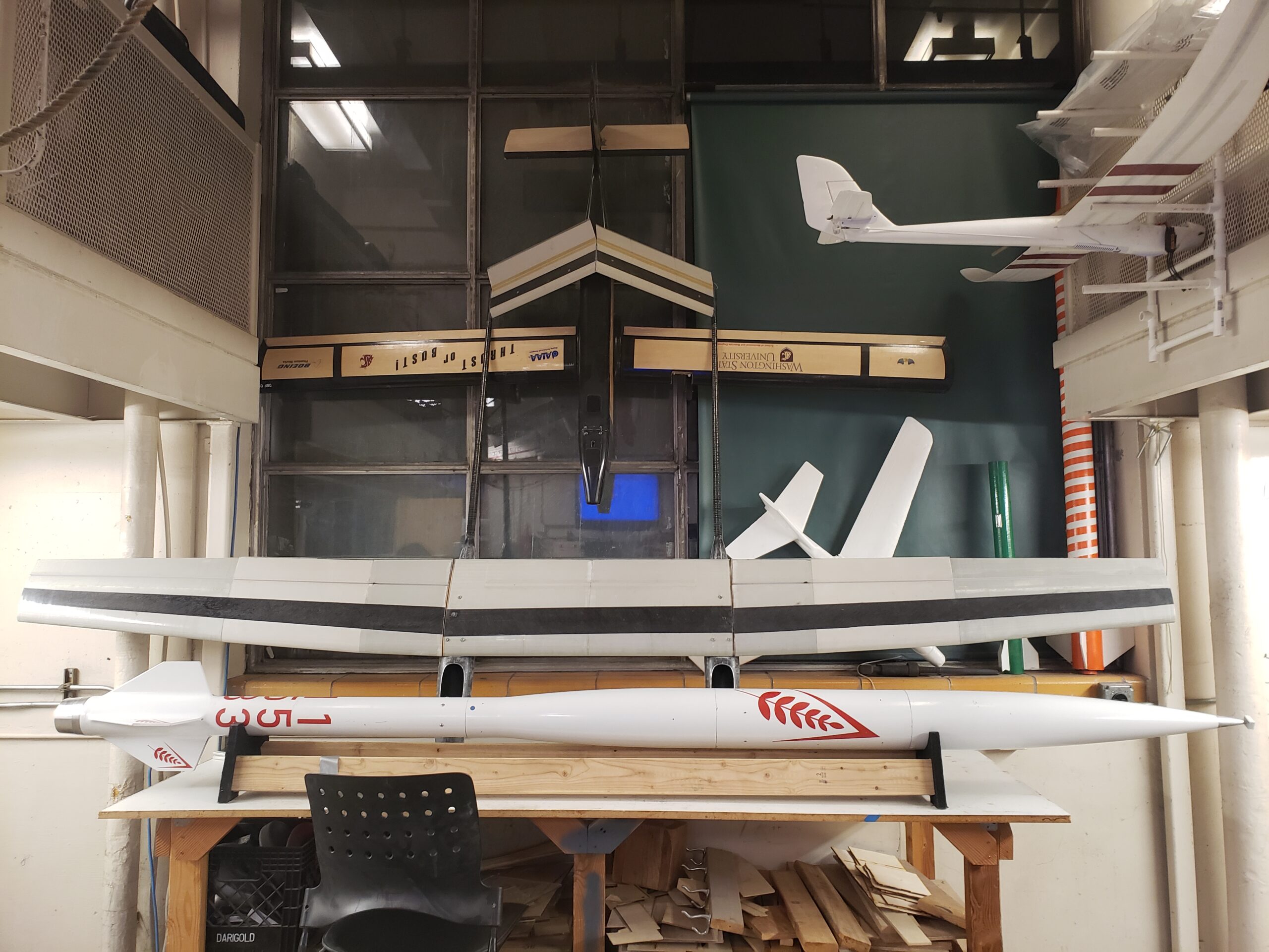
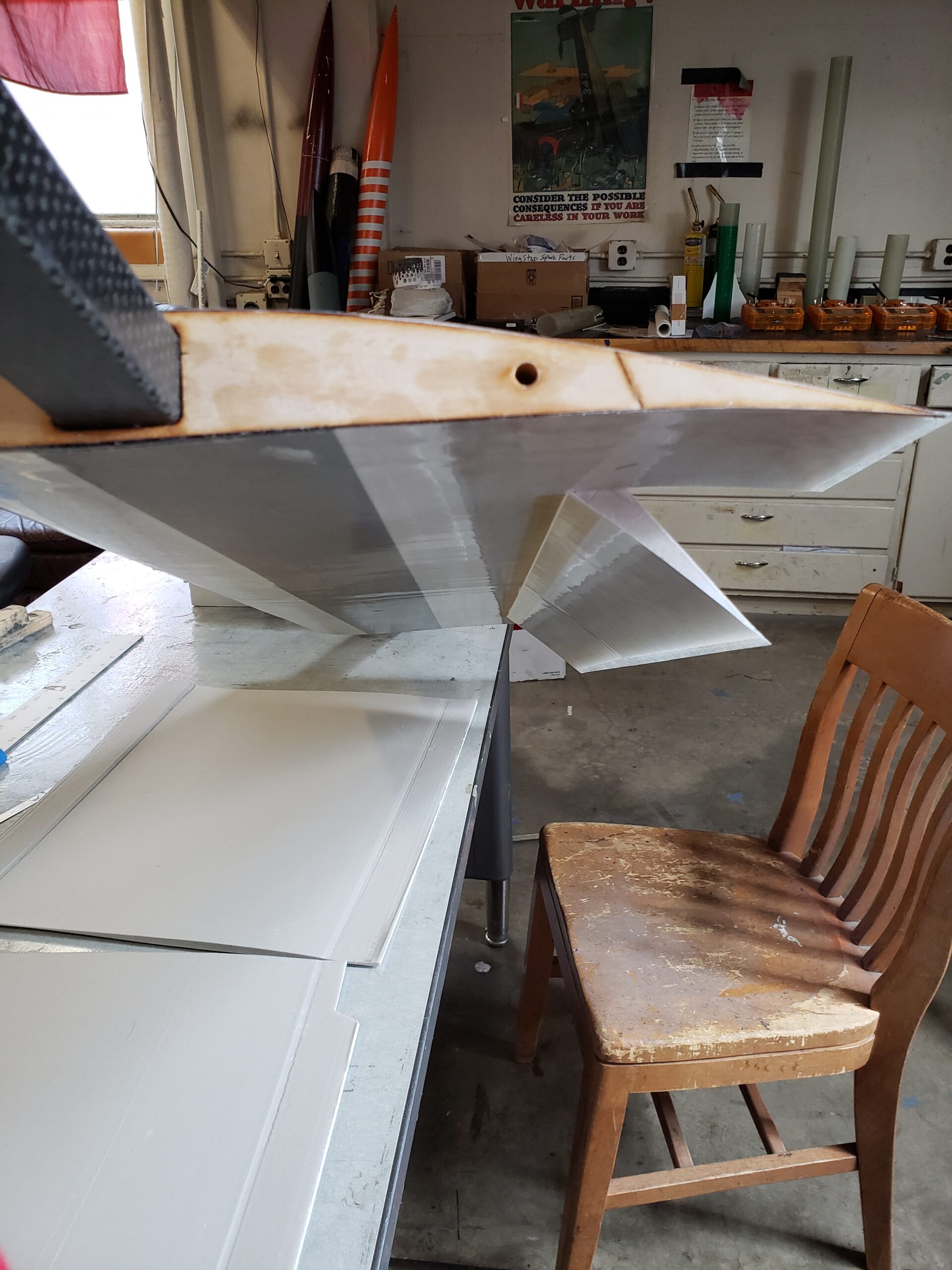
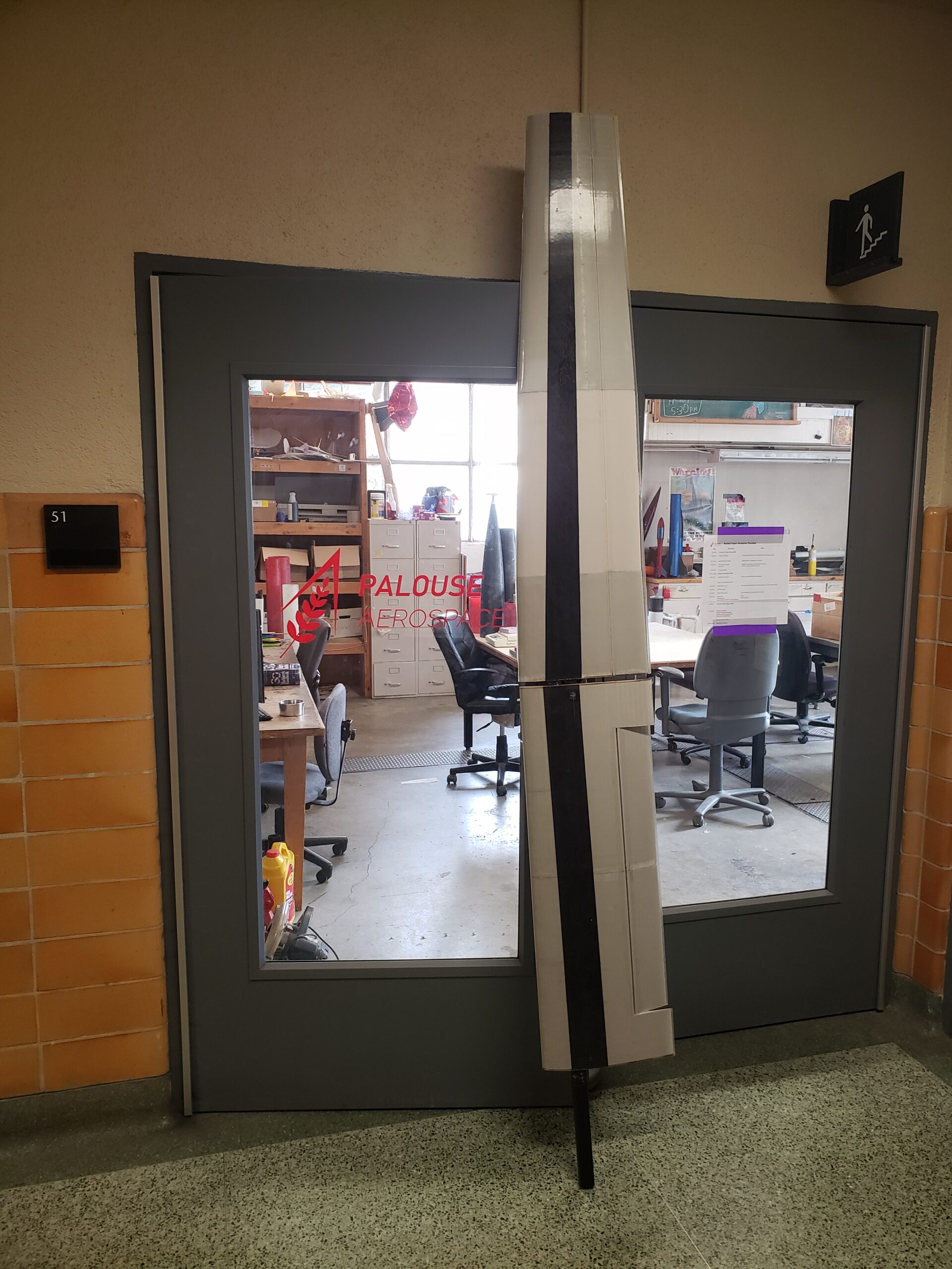
Given the large wingspan, the plane was designed with transportation in mind. The wing is easily separated into three wing sections, the V-tail slides off the booms, and the fuselages can be unbolted from the center wing section.
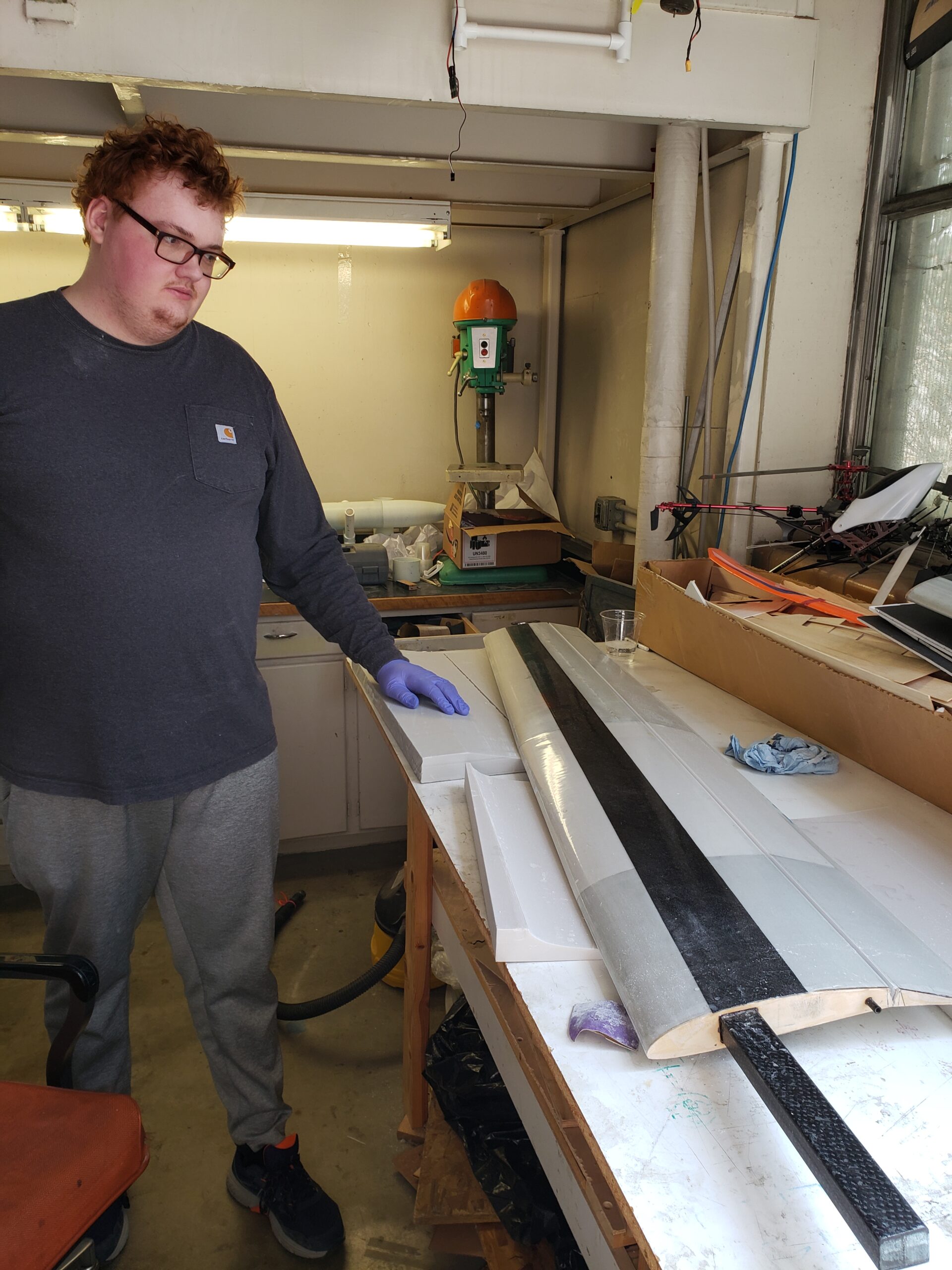
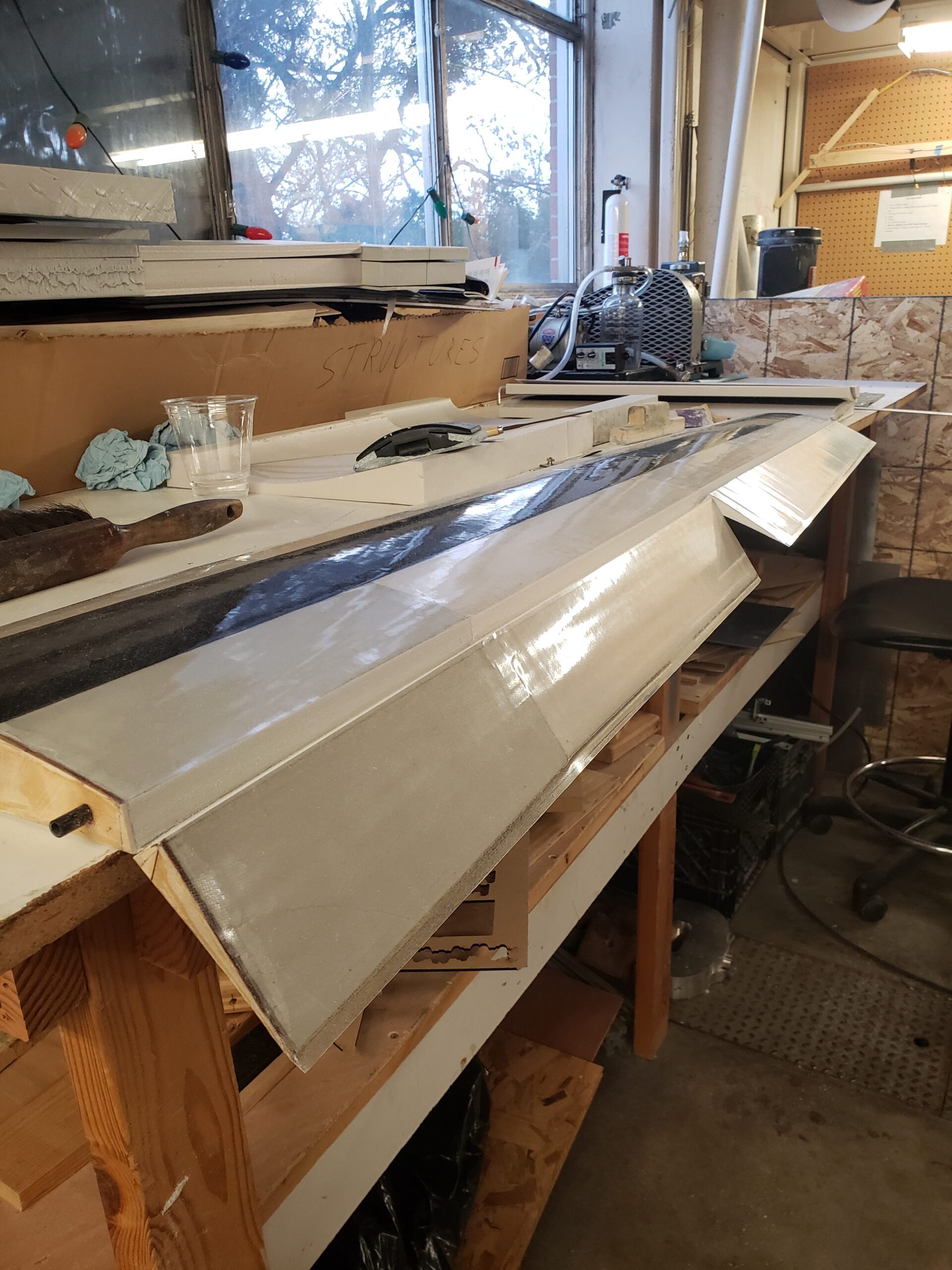
Construction
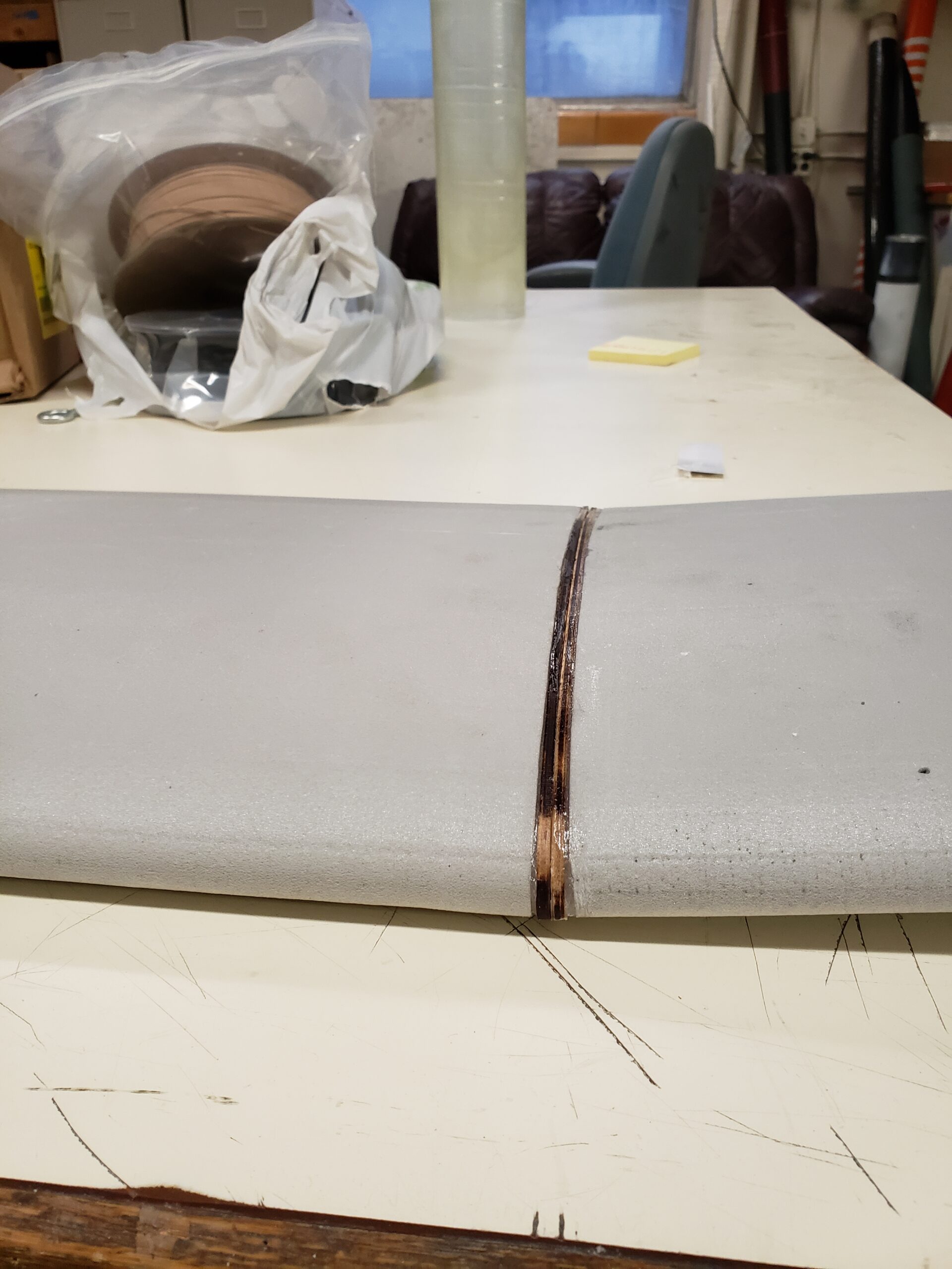
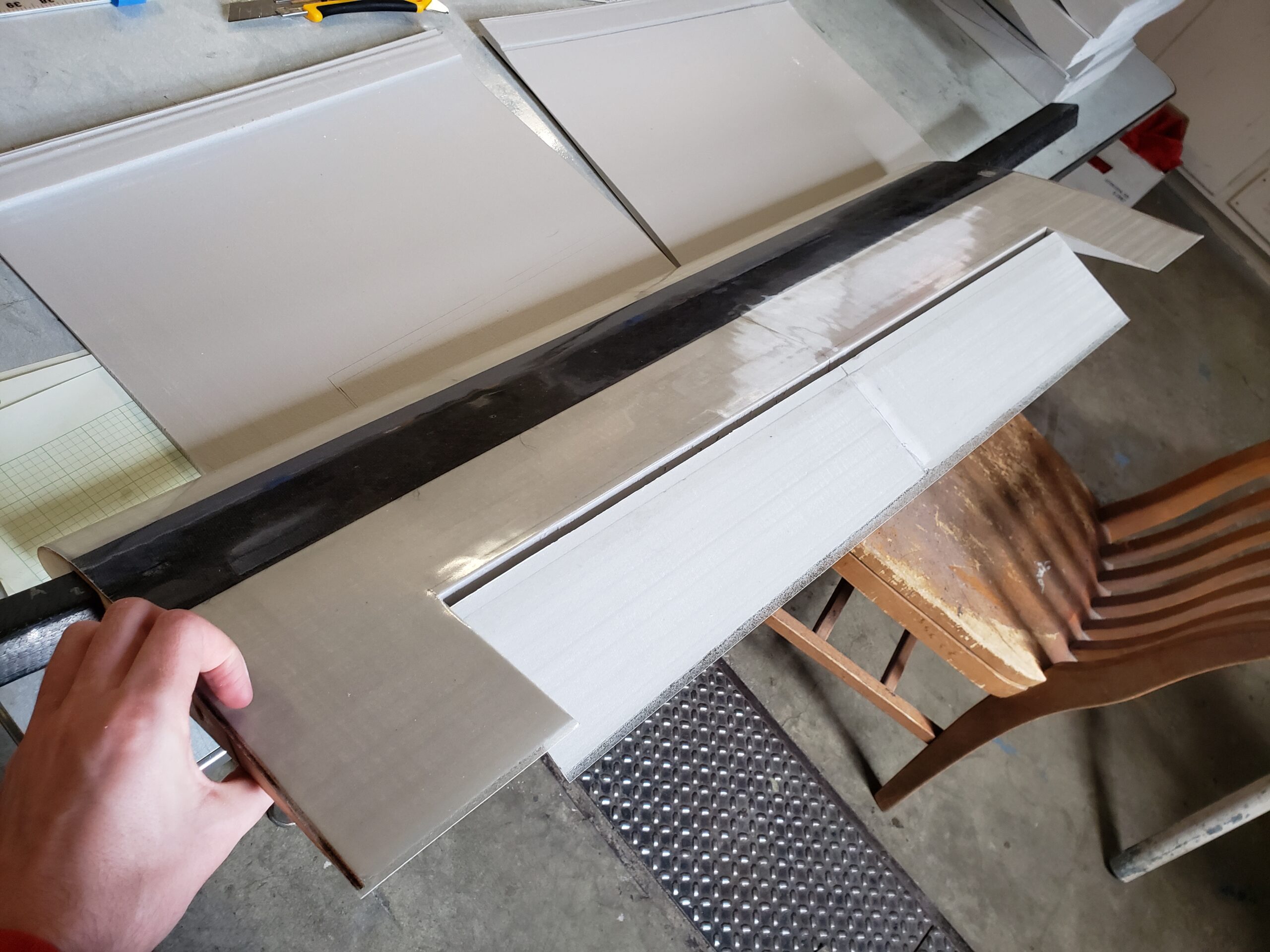
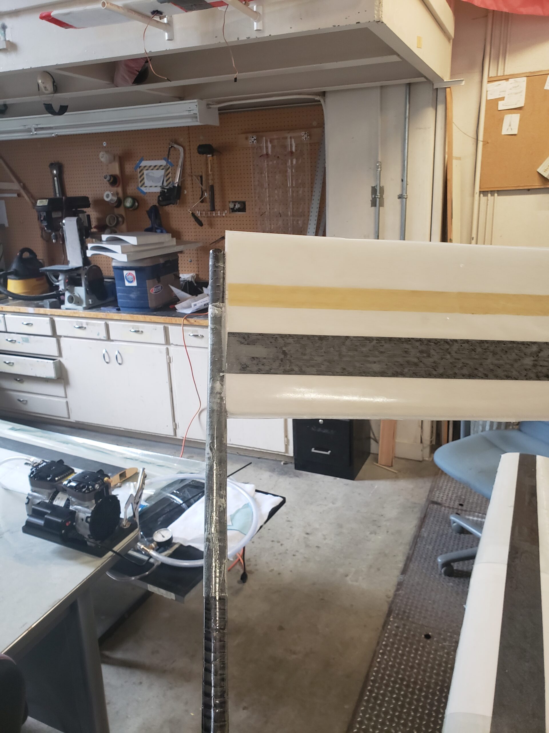
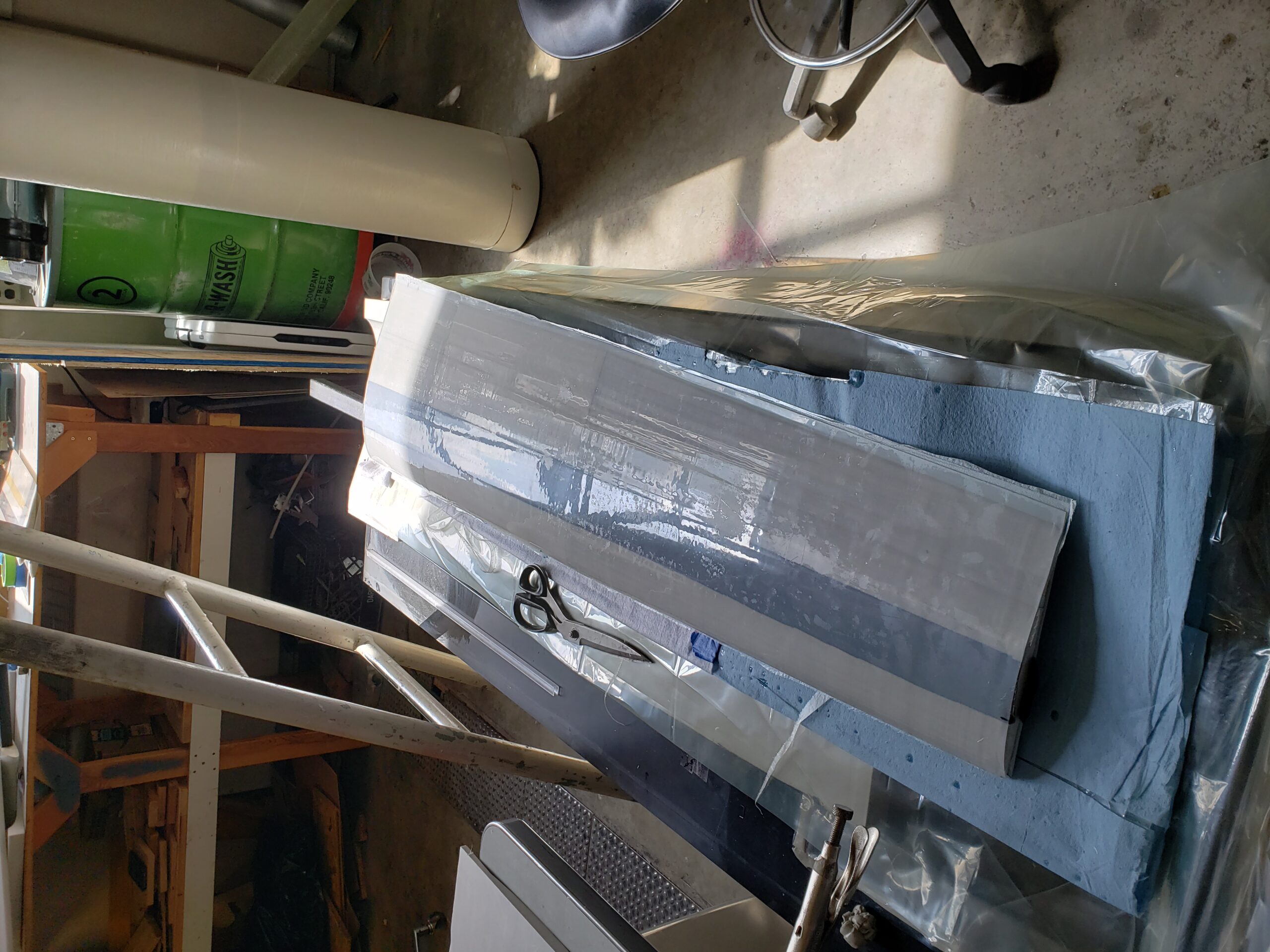
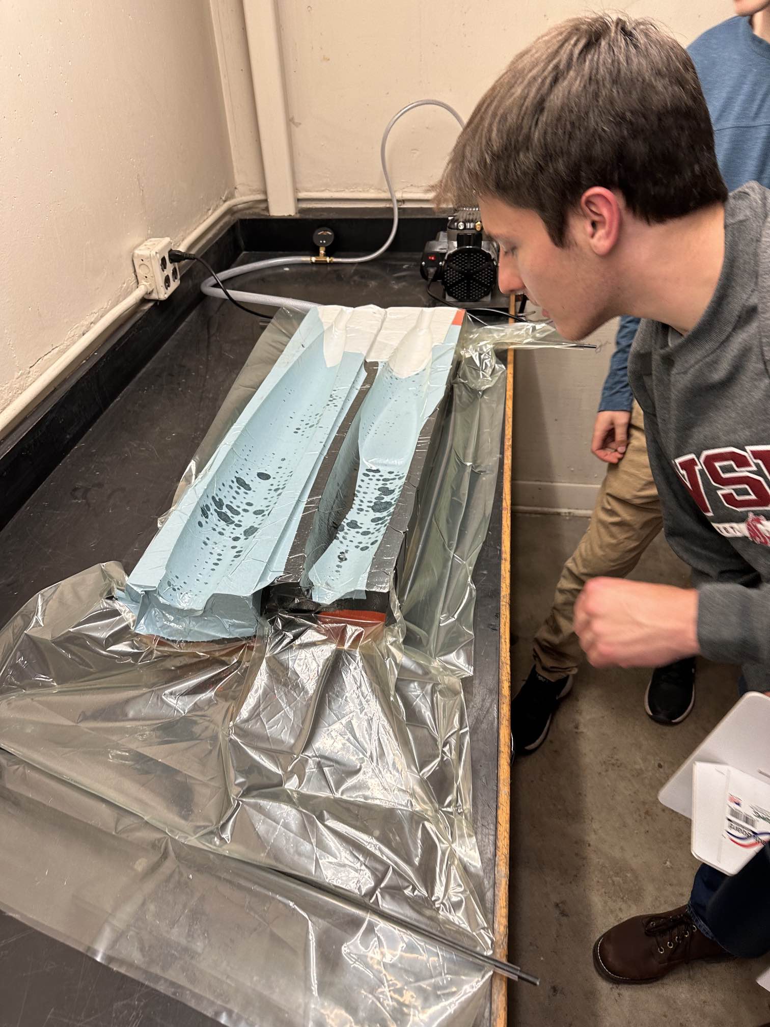
The lifting surfaces are vacuumed bagged fiberglass and epoxy with a unidirectional carbon fiber spar. The skin is 5 oz fiberglass with a 4.1 oz carbon spar. The core is CNC hotwired 30 psi XPS insulation foam from Pullman Building Supply. The hinges are 1.4 oz/yd^2 bidirectional strips of Kevlar bagged into the surface (known as Kevlar live hinges).
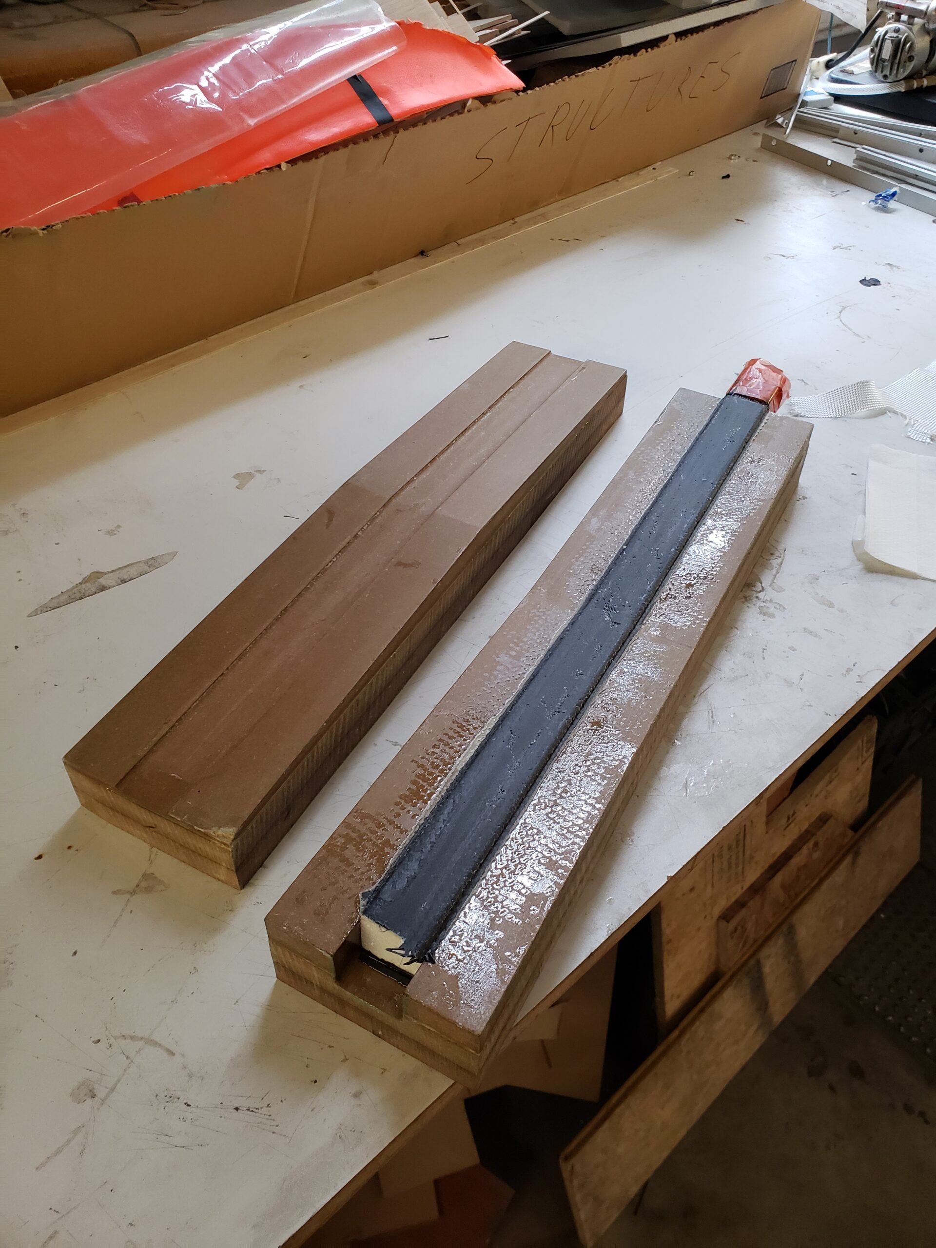
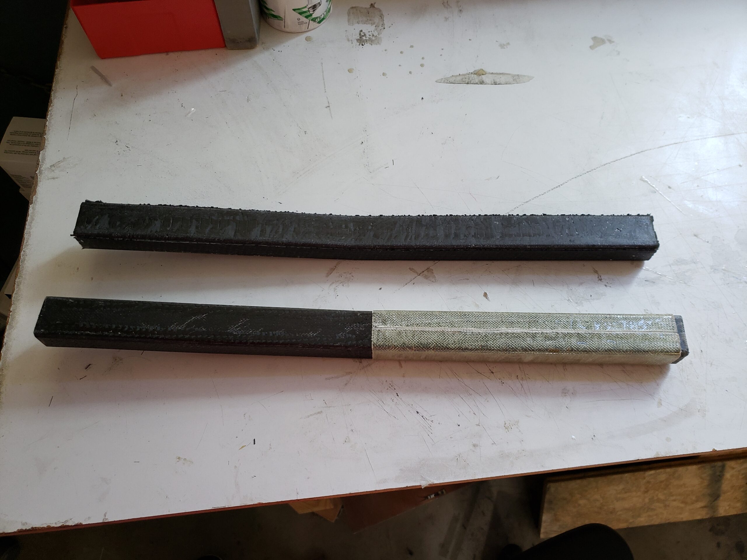
The wing removable section of the spar that transfers load from each section of the wing is made from unidirectional carbon fiber on the top and bottom of a slightly oversized foam core with a layer of 10 oz carbon fiber at +-45 degrees. The oversized core applies pressure when pushed into the mold allowing us to avoid using vacuum bagging. Once removed from the mold, a joiner sleeve can be molded over the joiner for a custom fit. This sleeve is then installed inside the foam core before bagging. This results in a near-perfect fit without relying on expensive one-off tooling.
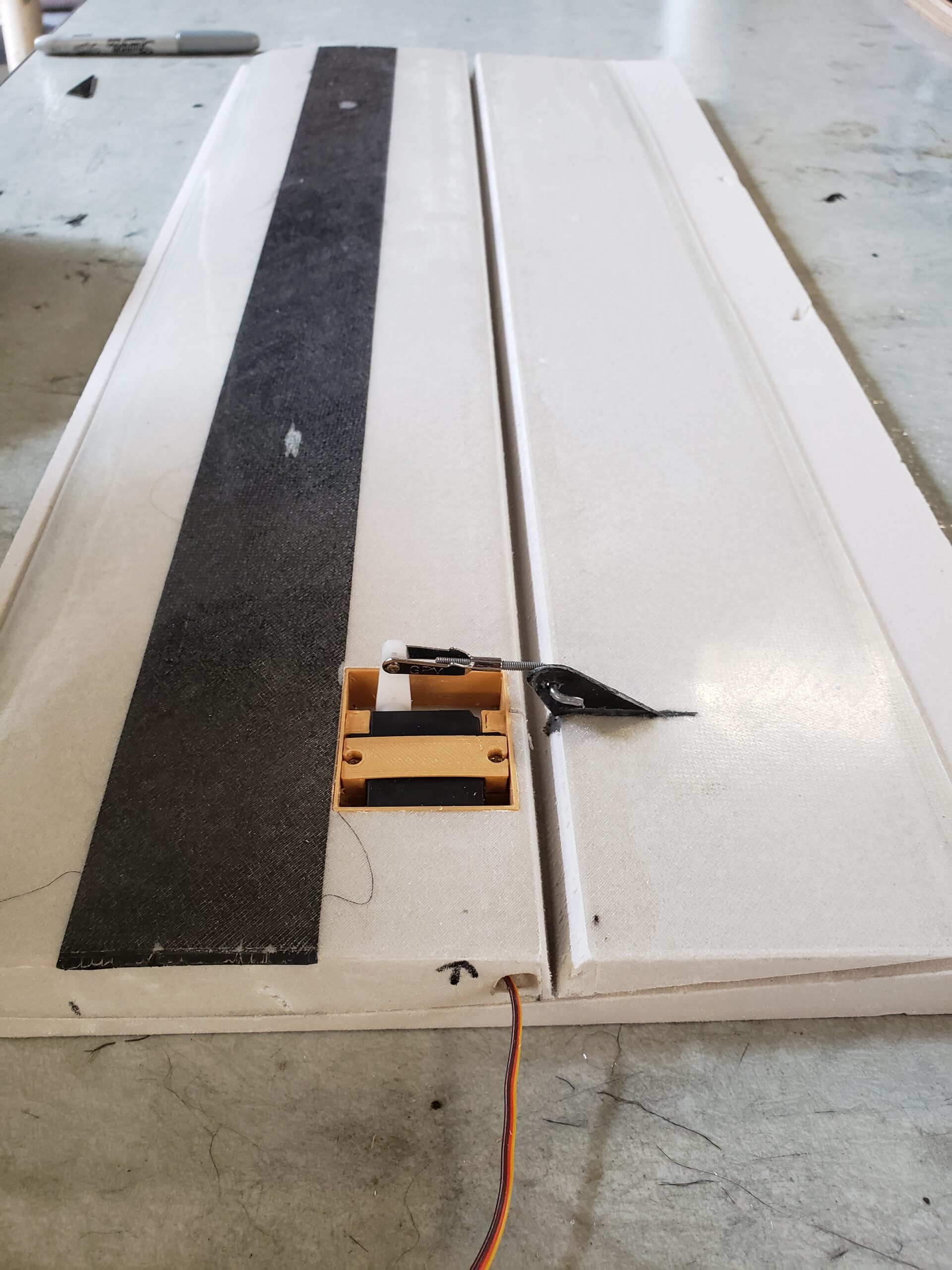
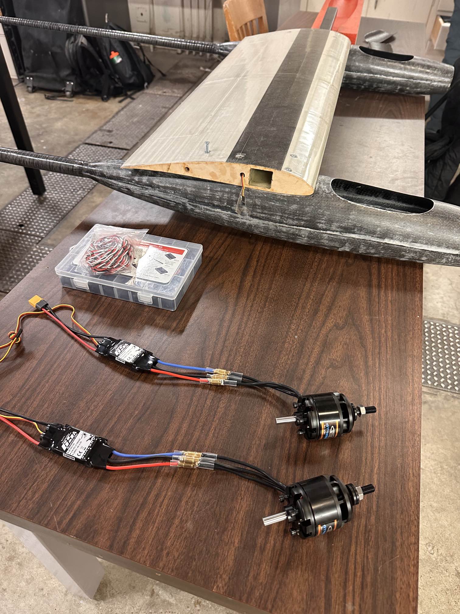
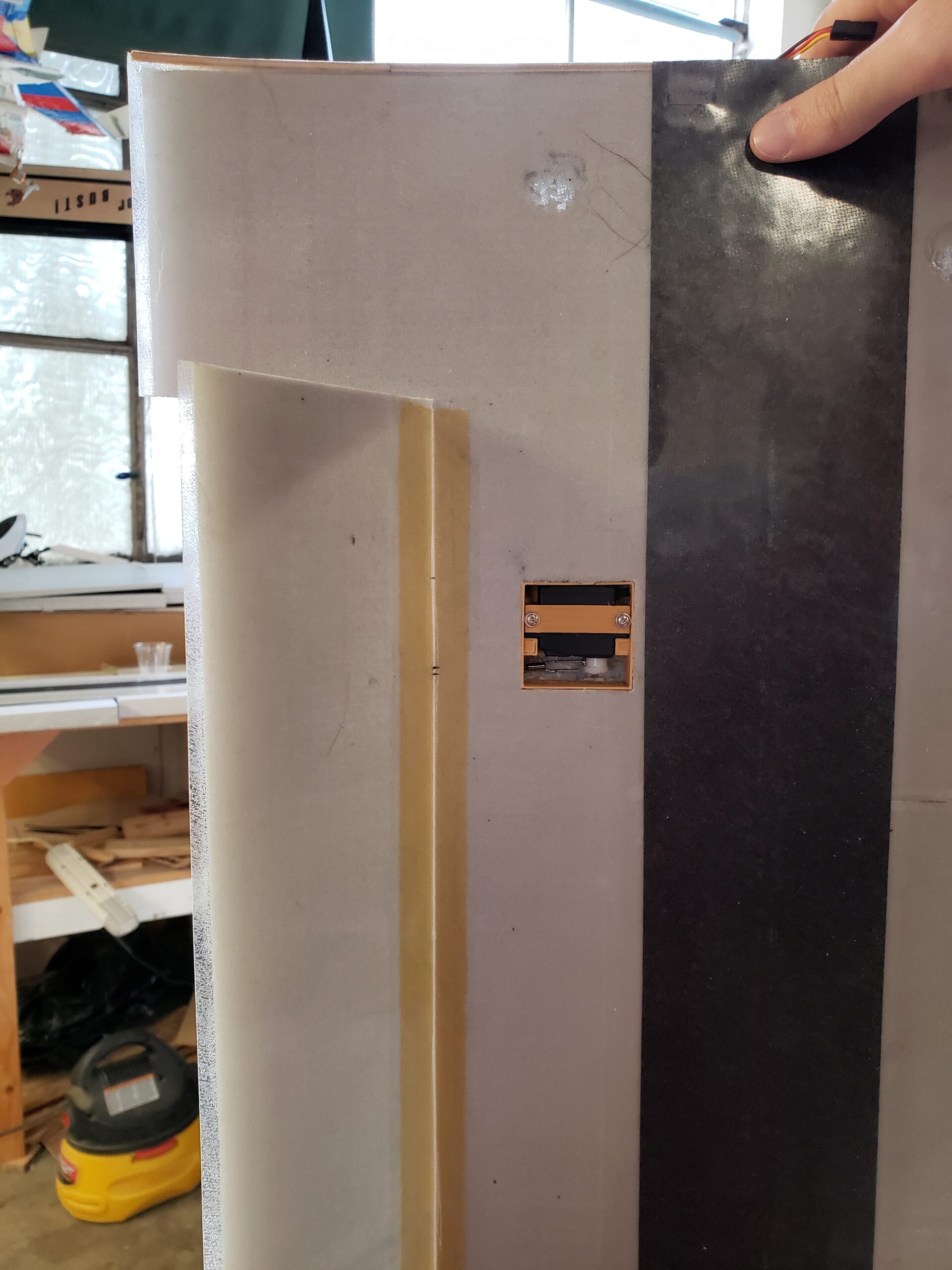
There are 7 servos used for control surfaces. The three servos used to control the center flap and the two flaperons have internal linkages that prevent damage and reduce drag at the cost of increased installation time. All servos are mounted just in front of the hinge which prevents issues associated with long control rods.
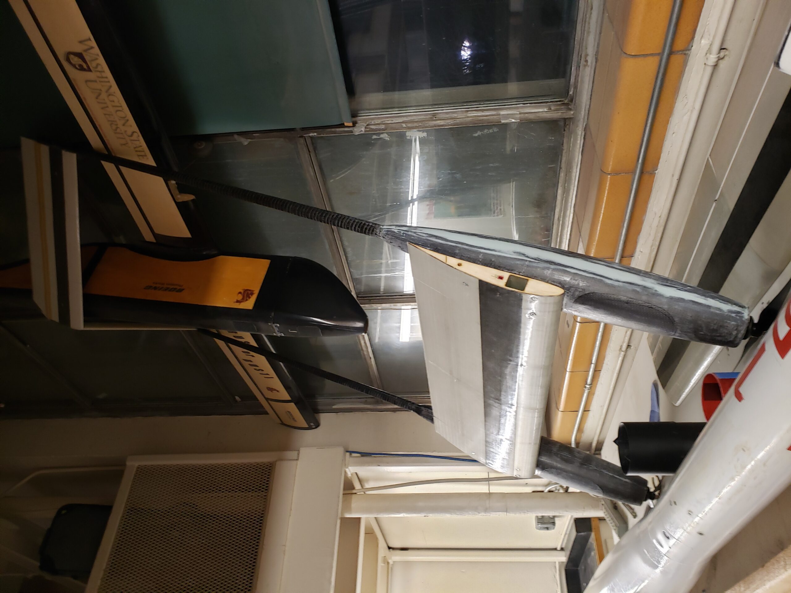
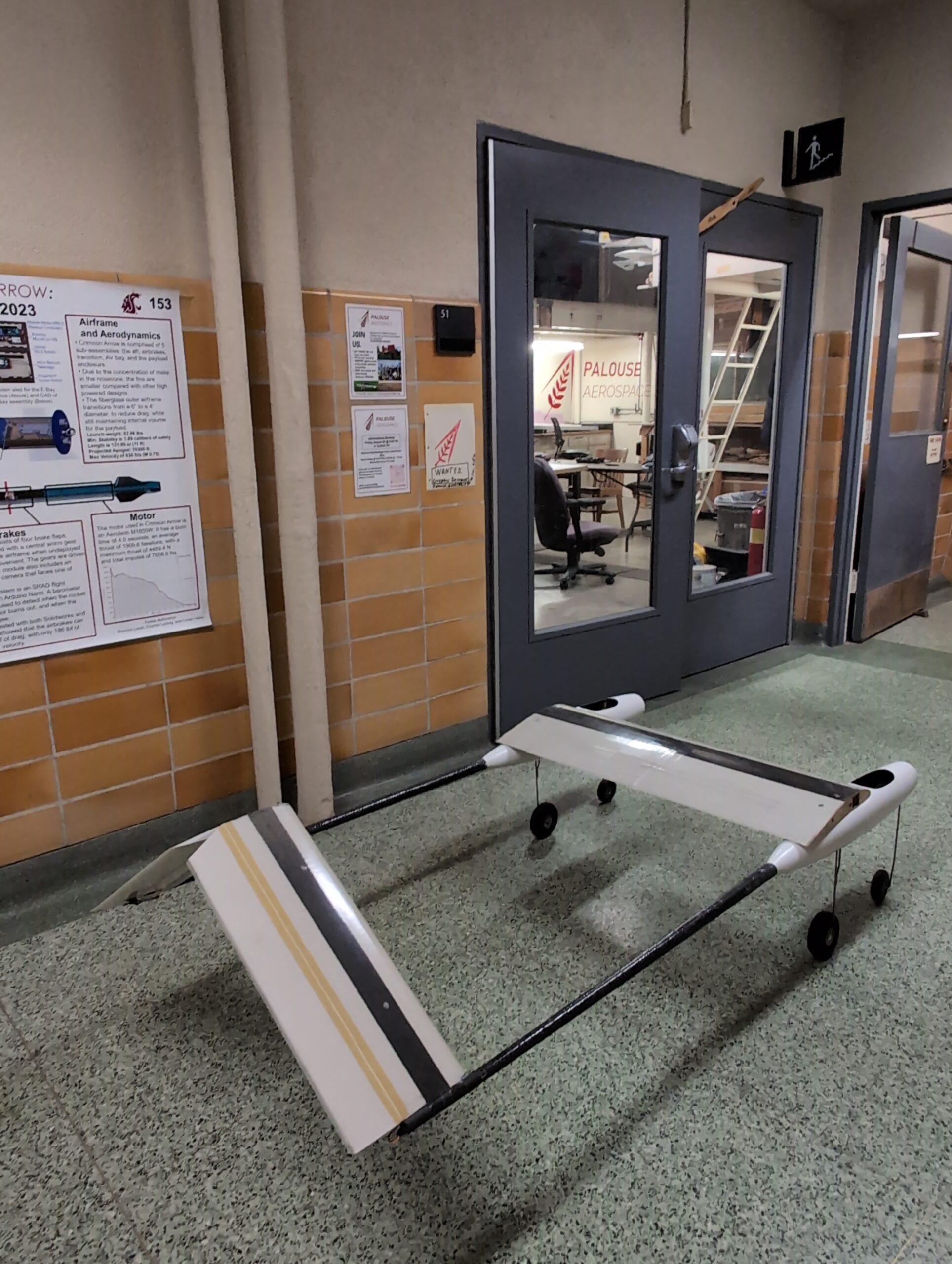
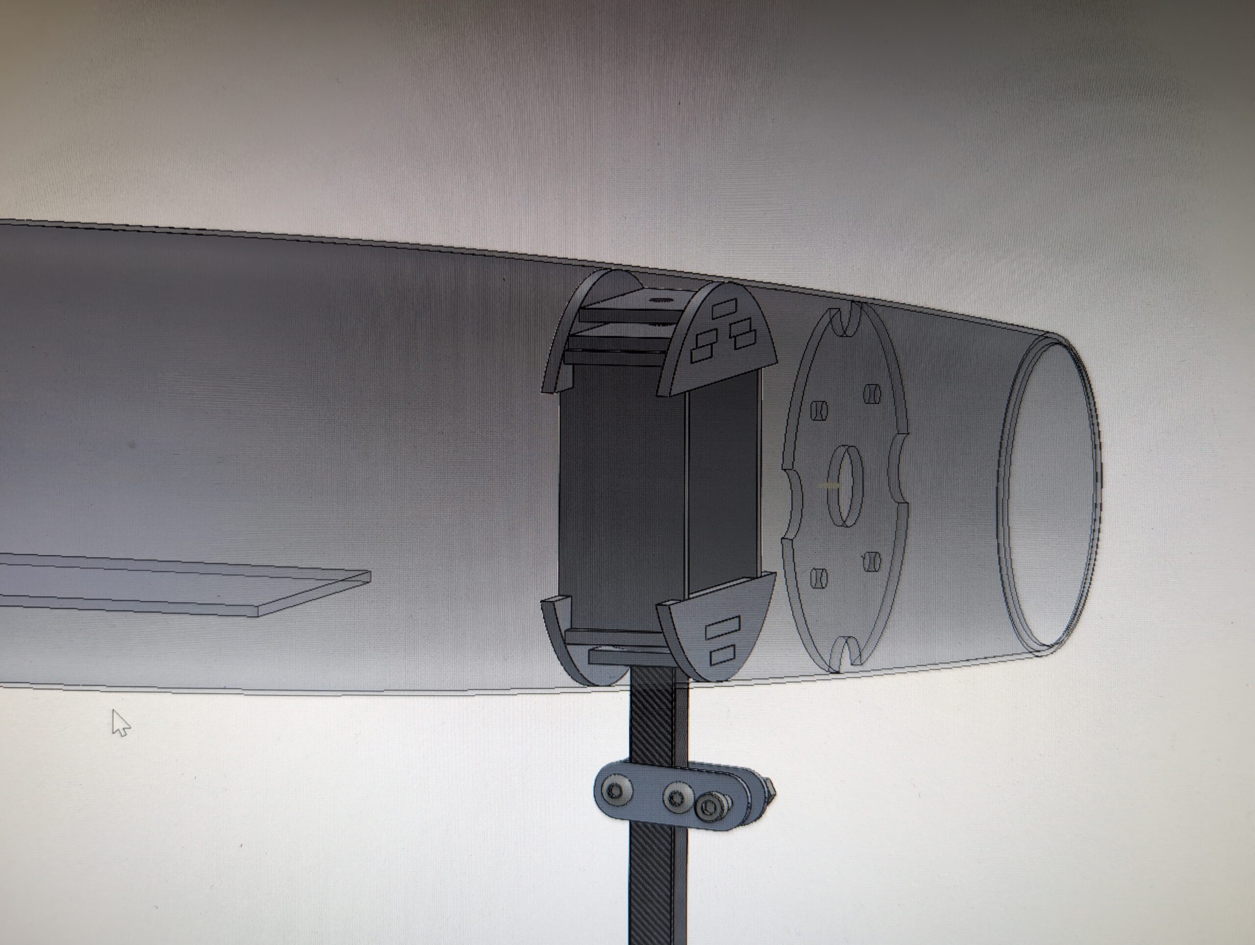
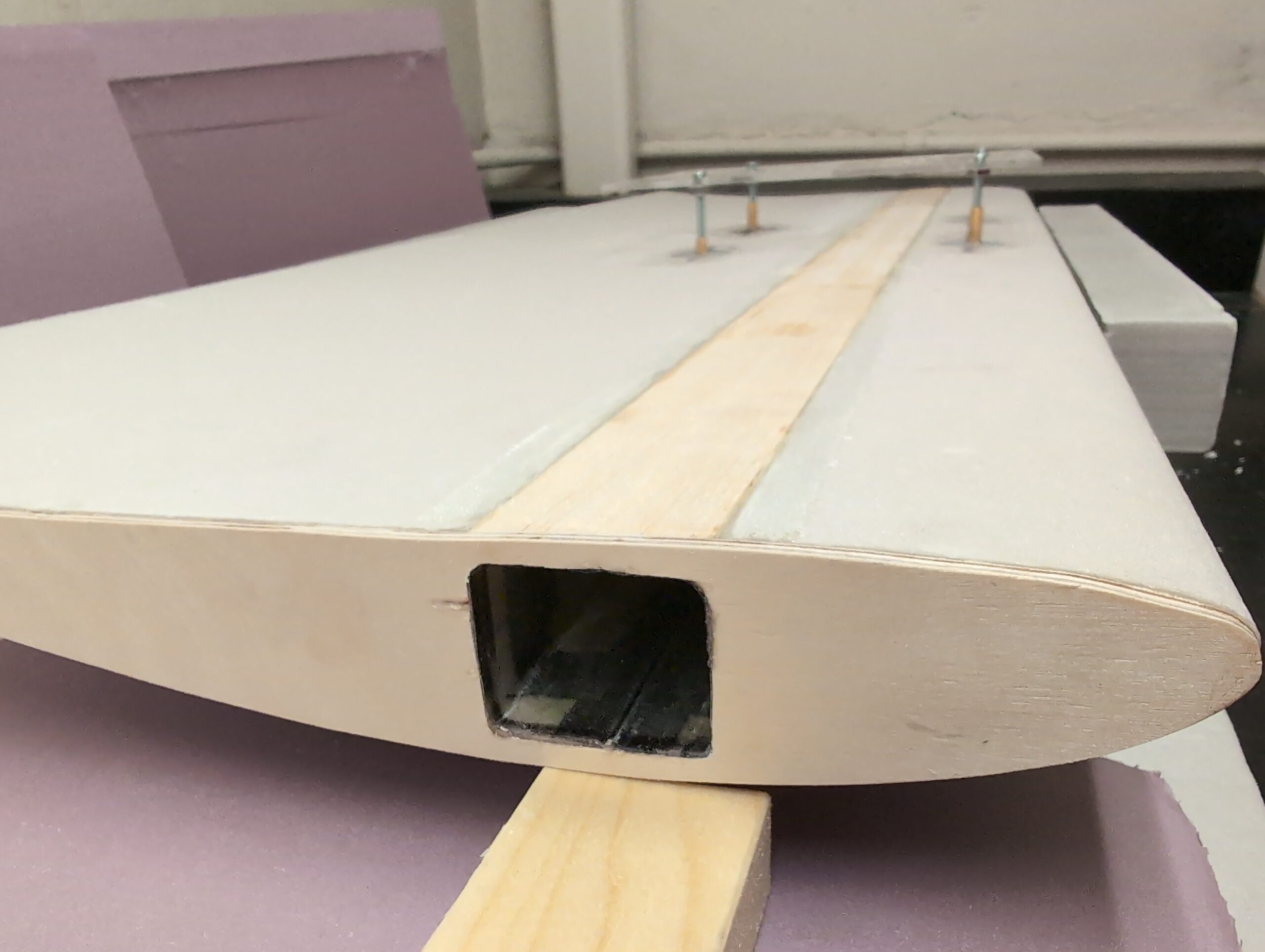
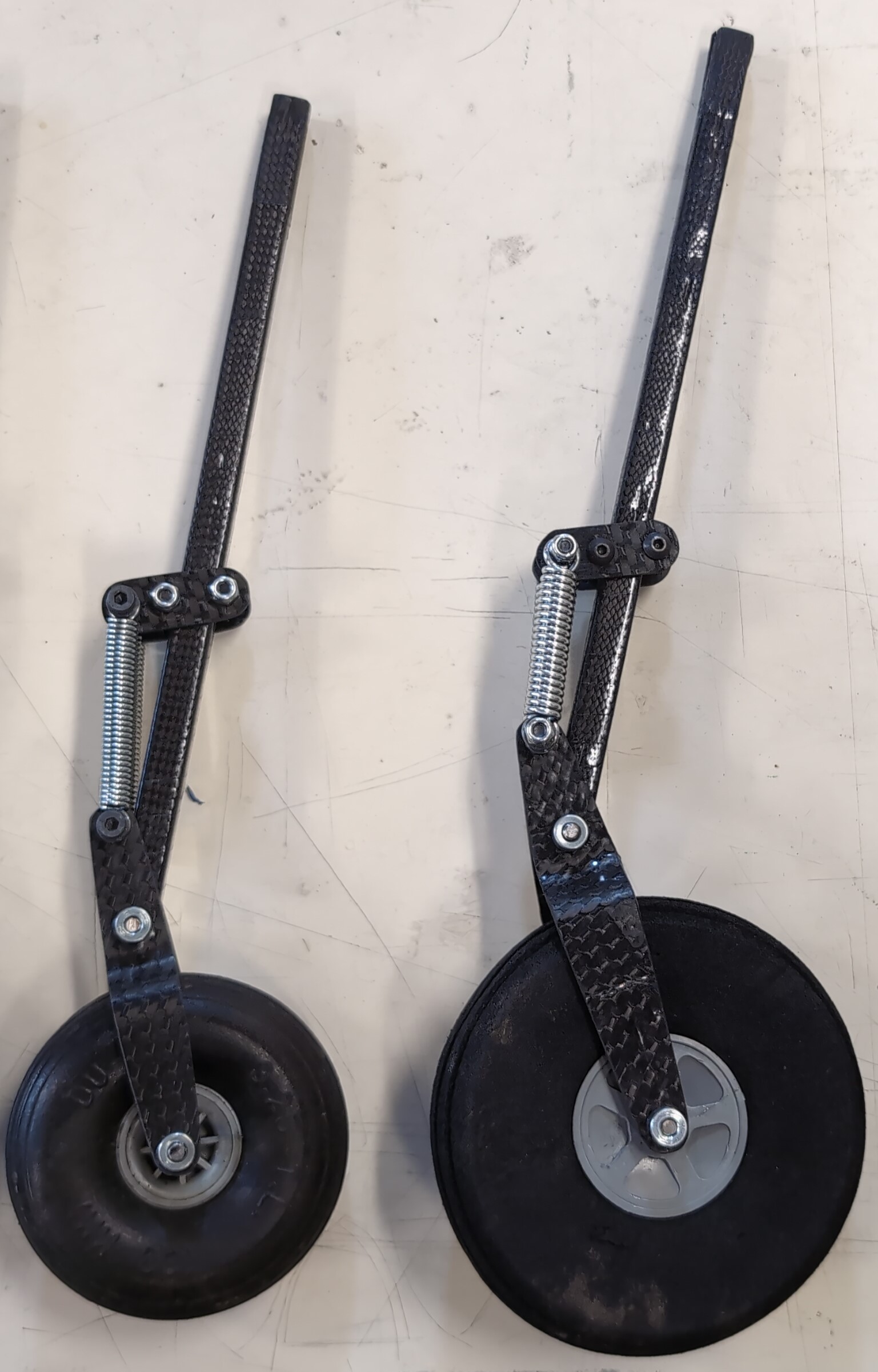
The four landing gears must withstand hard landings and rough grass runways while the plane is fully loaded at 30 pounds. This turned out to be more difficult than we initially realized. After several iterations and almost 3 weeks of testing we settled on a compites design with large compression springs to allow the wheel to deflect over 1.5 inches before bottoming out. This greatly reduces the magnitude of the impact forces. The design is extremely simple which allowed us to fabricate it from pultruded square carbon rod, music wire, and custom carbon fiber laminates. A 3D printed mold provided the 2d profile required to make the lever arm laminate from one piece. The laminate of the lever arm is thickest around the pivot point and thinnest at the ends to improve the strength-to-weight ratio. The landing gear transfers the impact forces to bulkheads made from laser-cut plywood inside the fuselages.
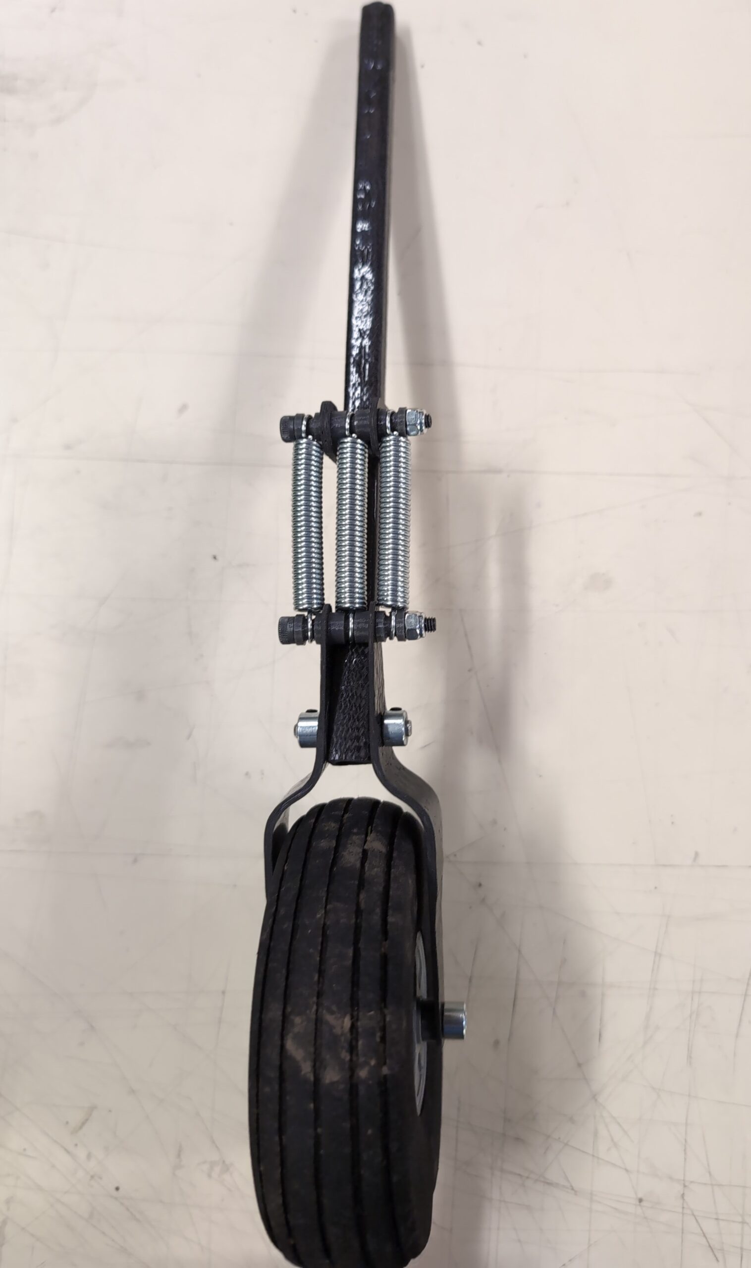
Landing gear front view
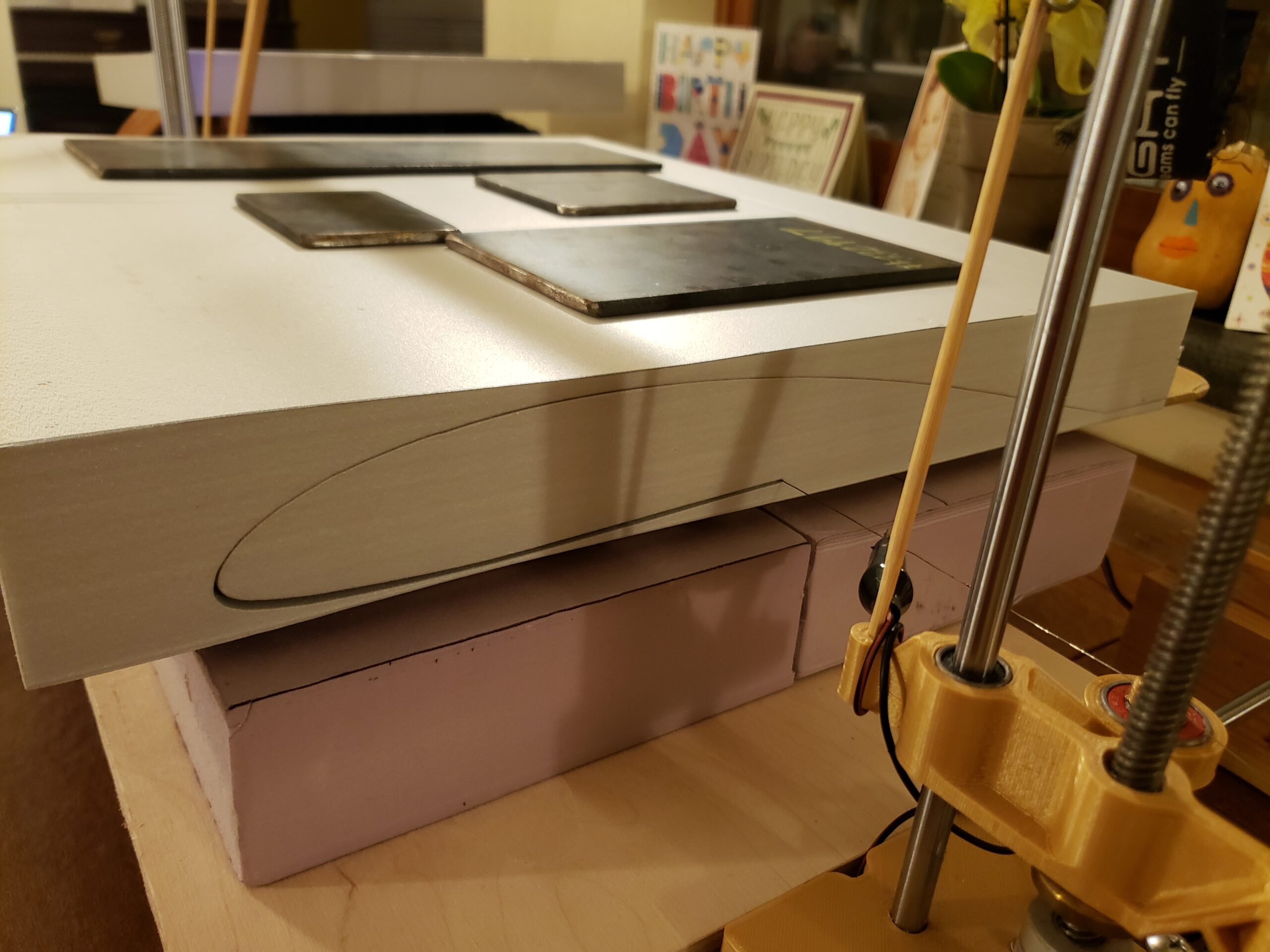
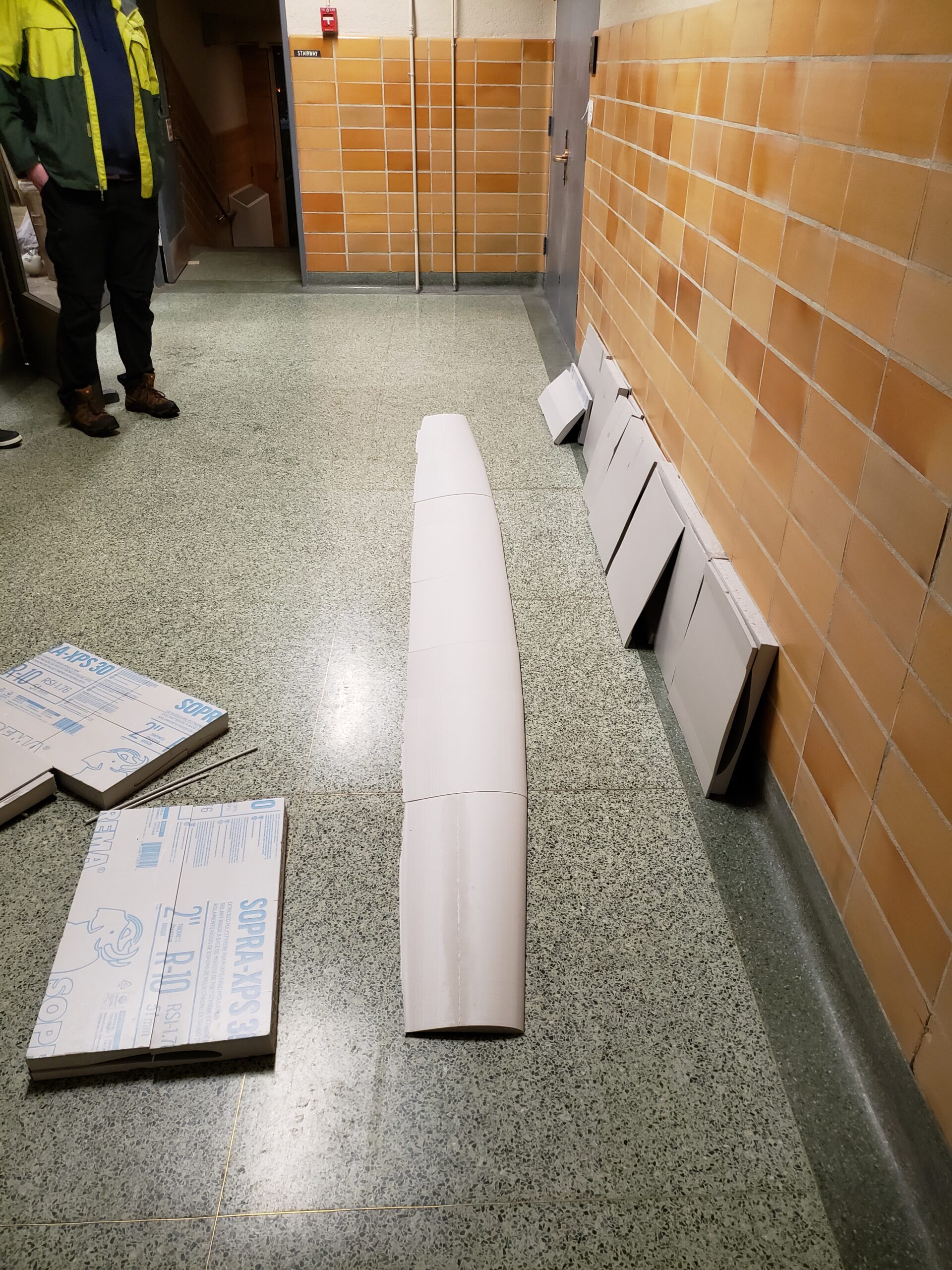
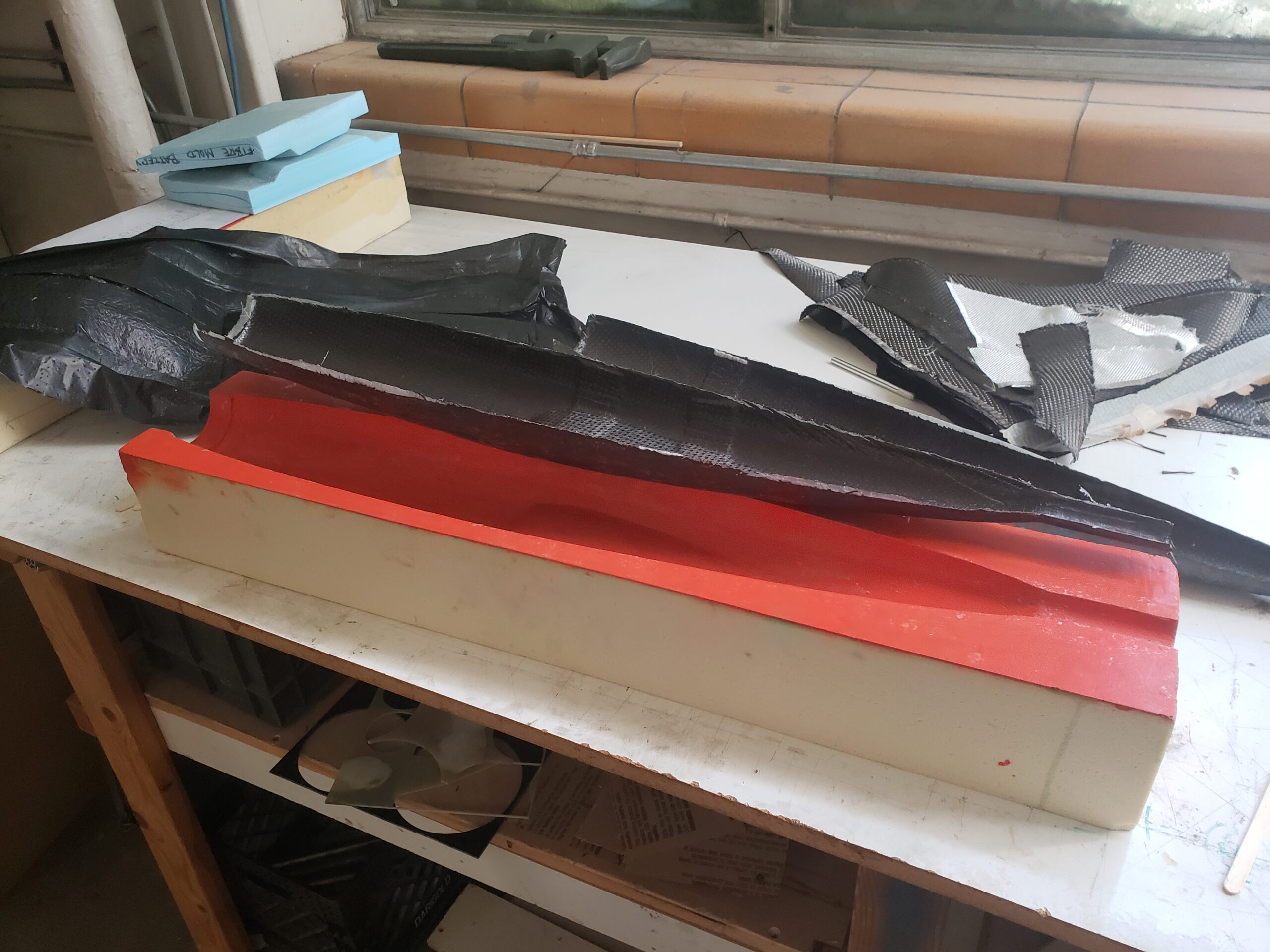
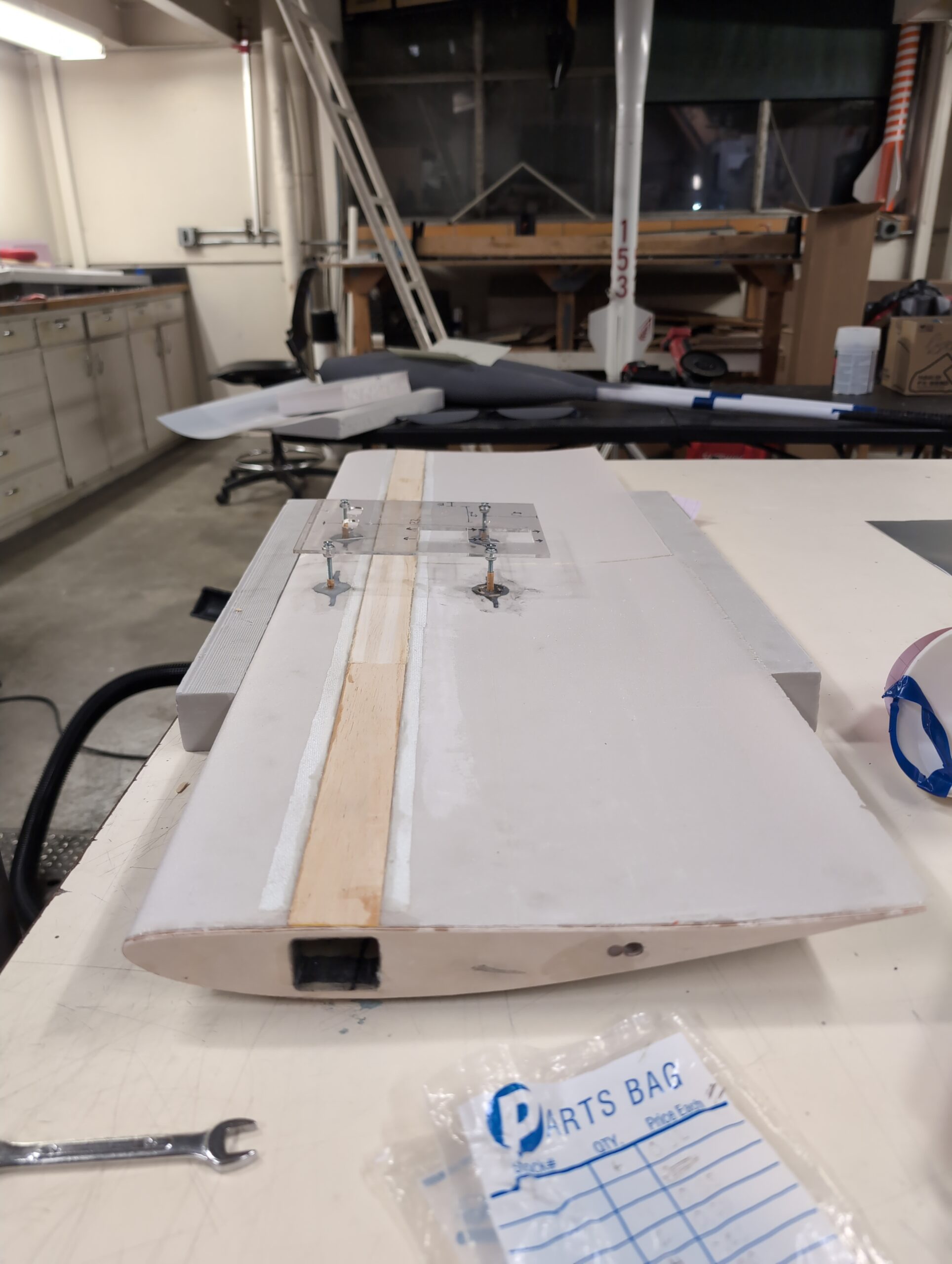
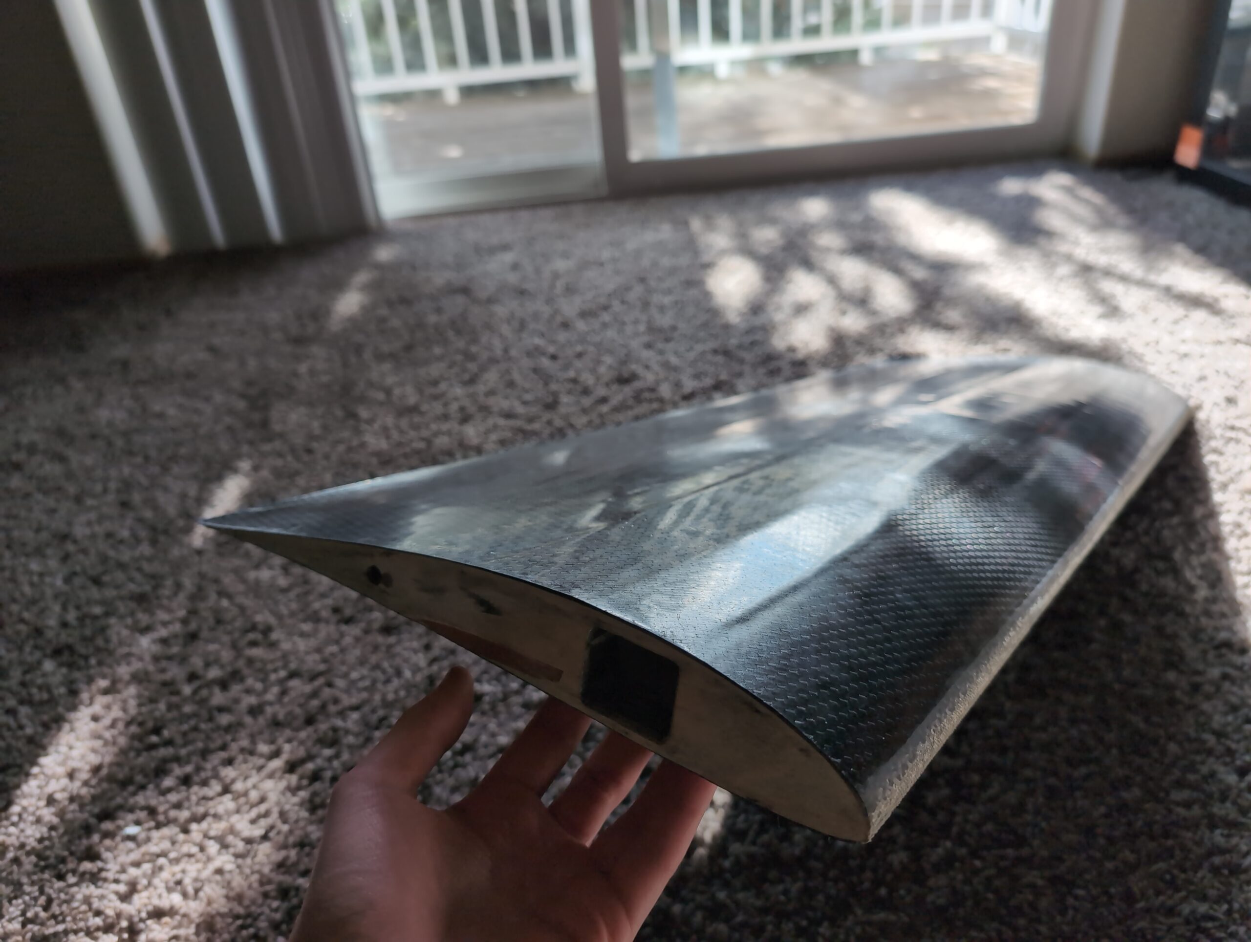
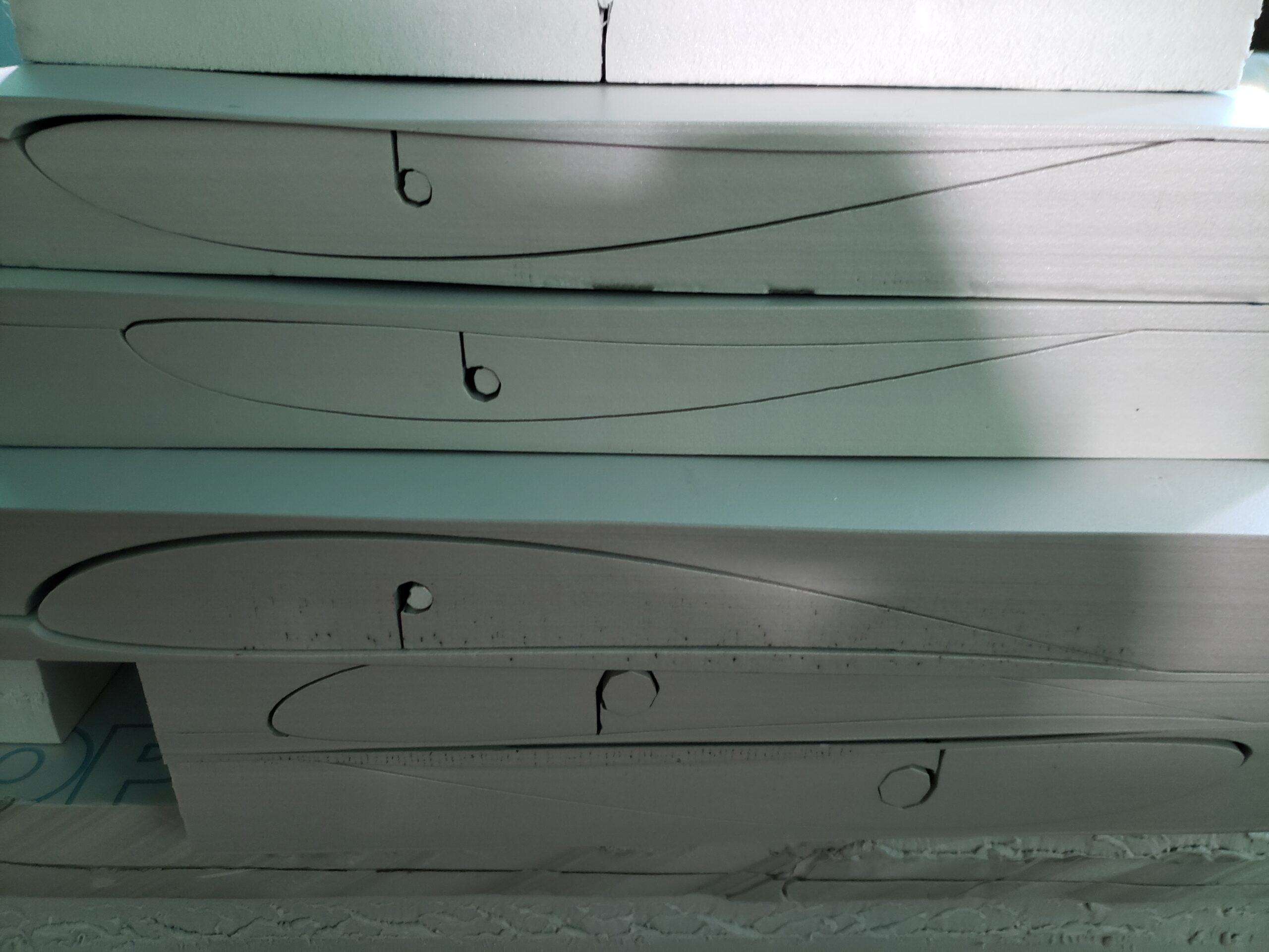
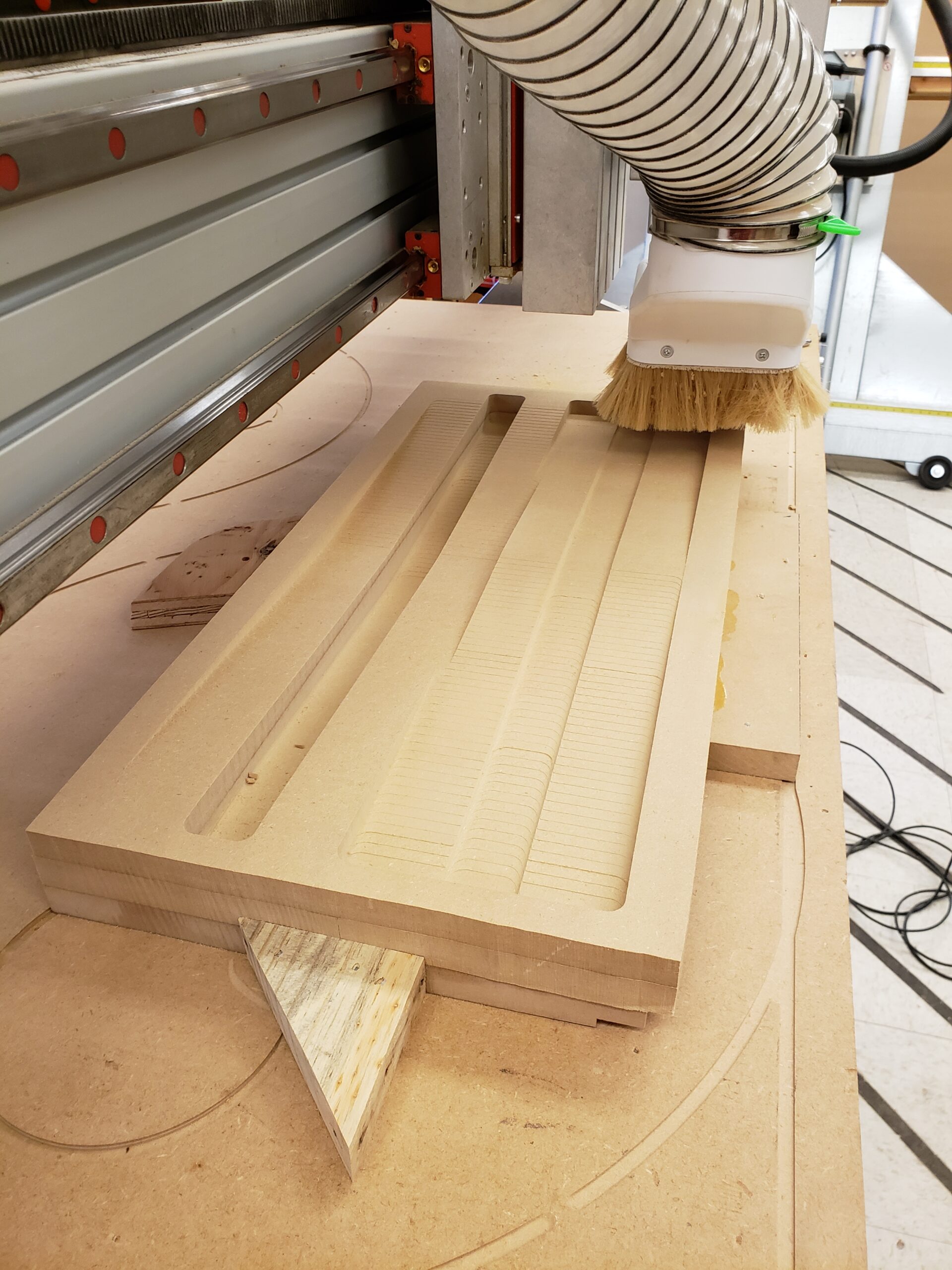
The fuselage mold and the first top fuselage part pulled from it
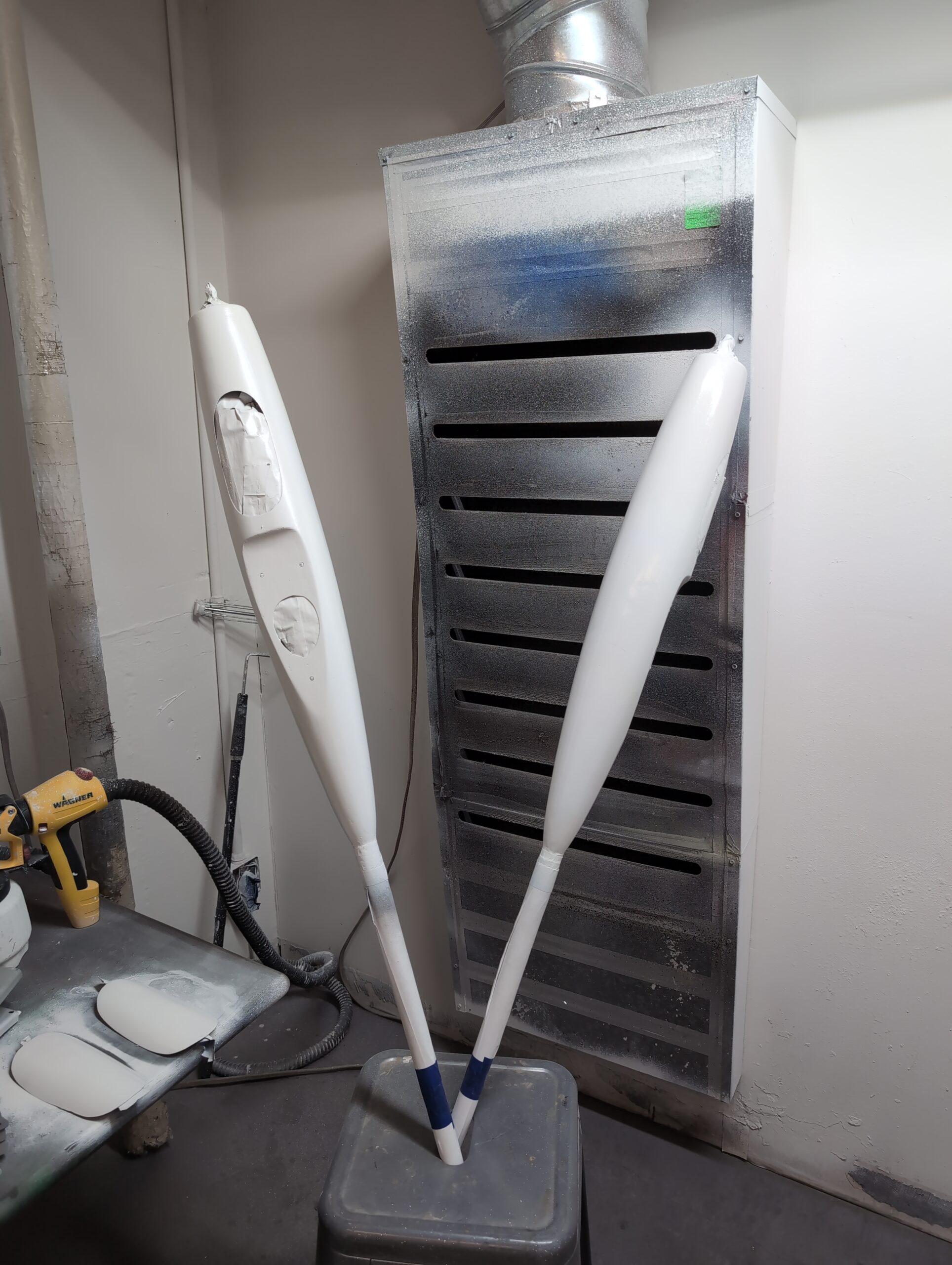
Fuselages and hatches during painting
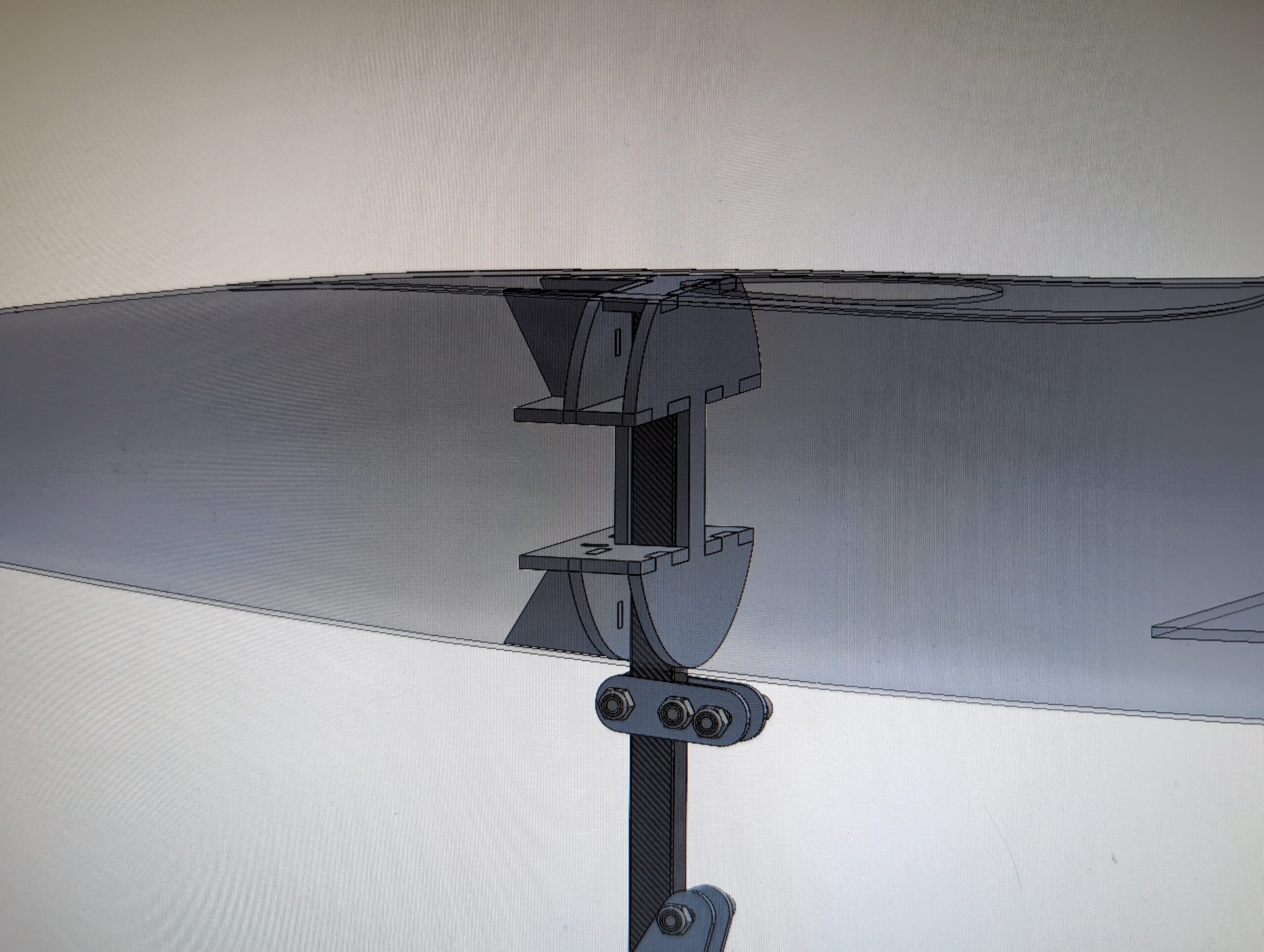
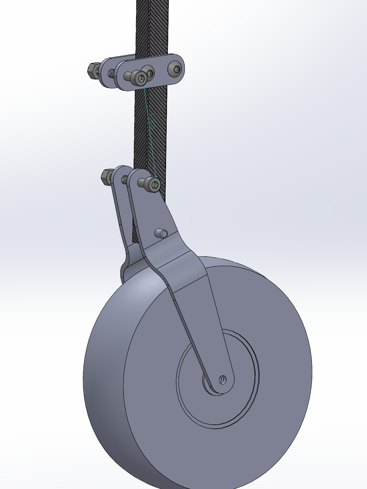
Landing gear side view
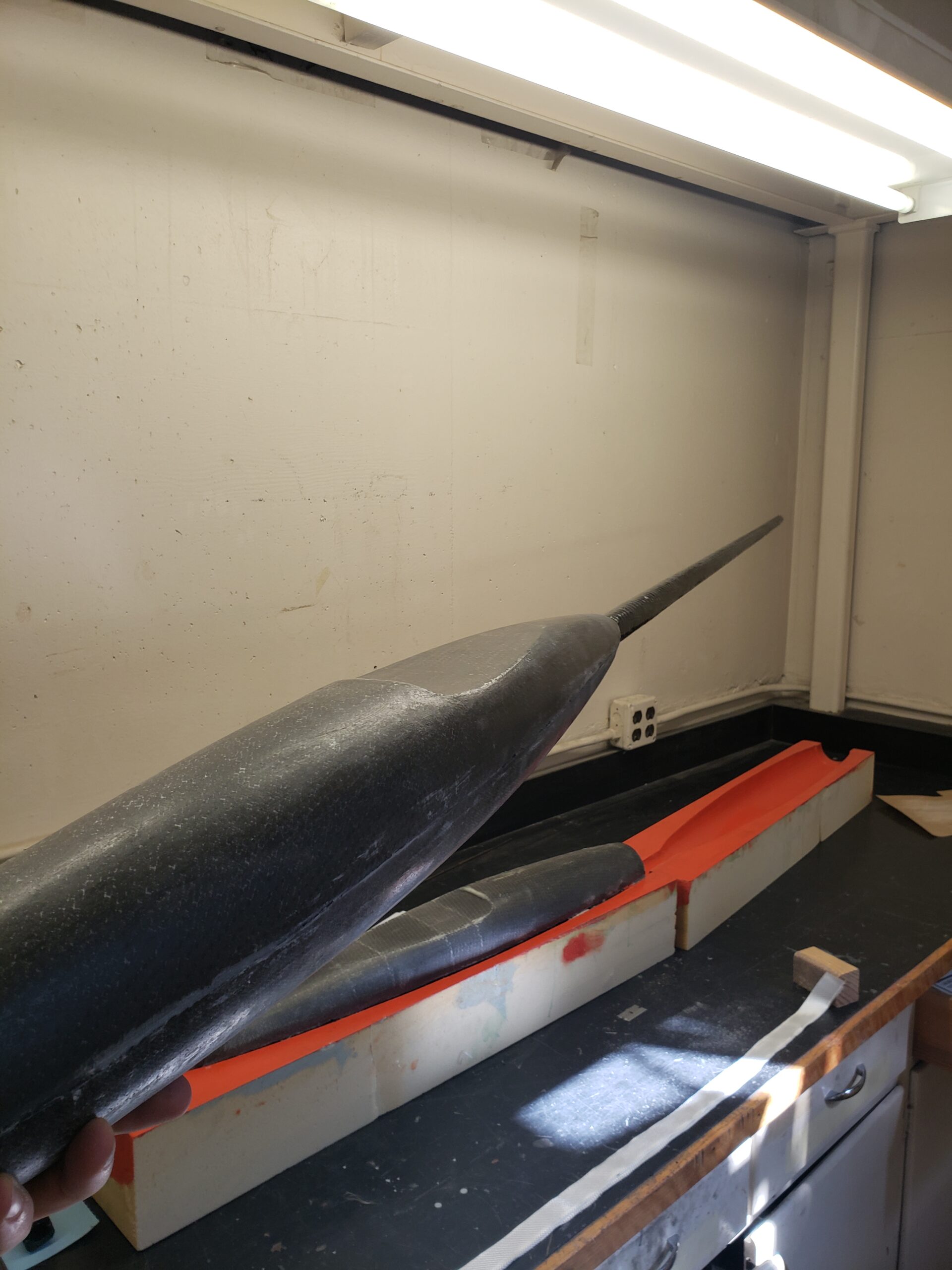
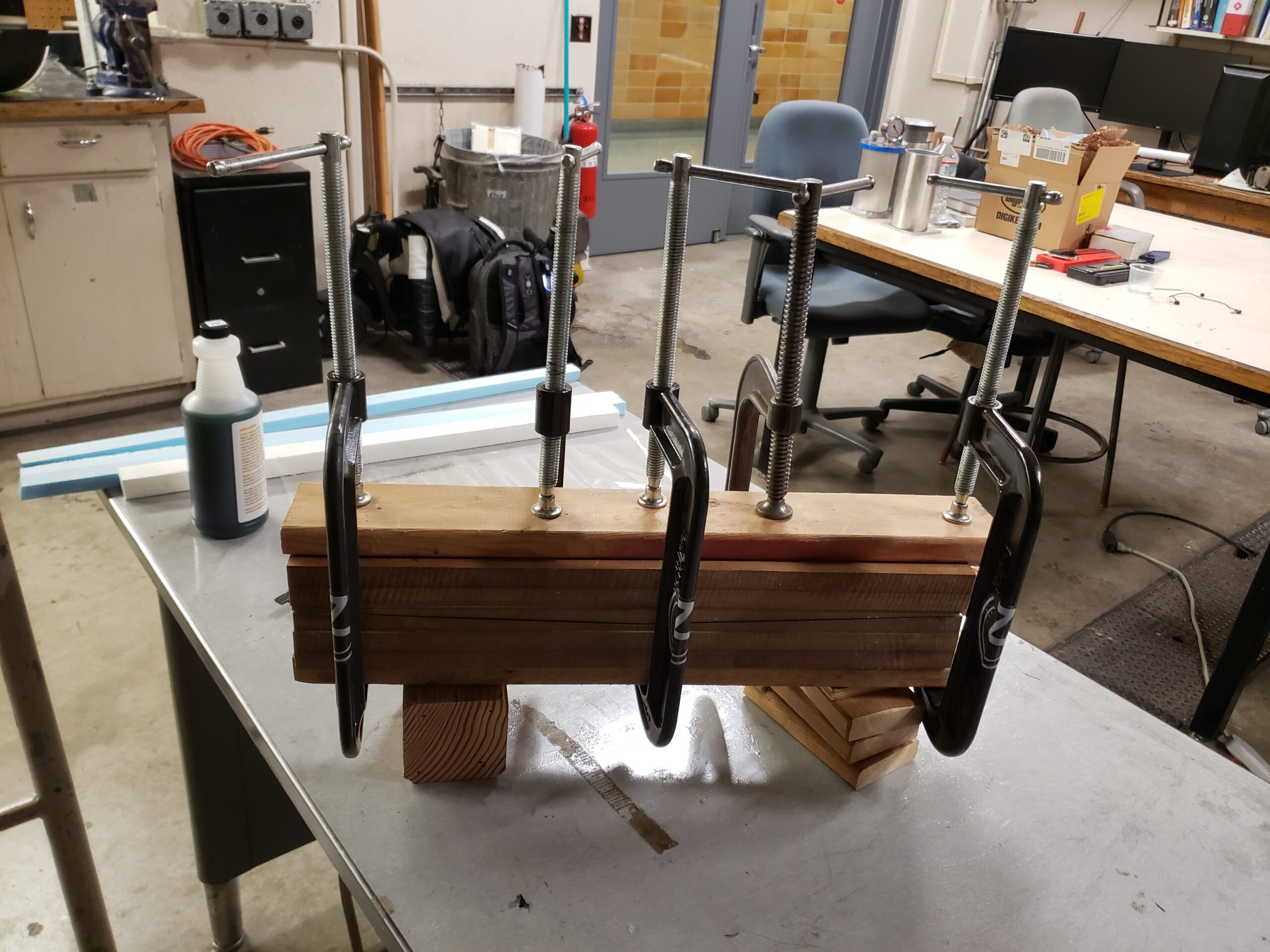
The first fuselage after bonding the top and bottom half together