Overview
Several club members have been interested in building solar-powered planes for a few years now. We would love to build a plane that can fly indefinitely using primarily power from the sun during the day and reserve power from batteries at night. This has been done successfully and there are a fair number of papers on the topic but even so, it is still a rather difficult task. We decided to work on the underlying techniques and technologies needed to build a solar plane with the hope of someday being able to make a solar plane capable of flying through the night. Given our experience with building composite planes, we choose to design and build a 2-meter solar plane capable of flying throughout the day during ideal conditions. This is a very achievable task because only a small battery is required (technically no battery is needed). By designing and building this plane we have gained a lot of experience with solar cell encapsulation, solar panel electronics, and autonomous thermal soaring algorithms.
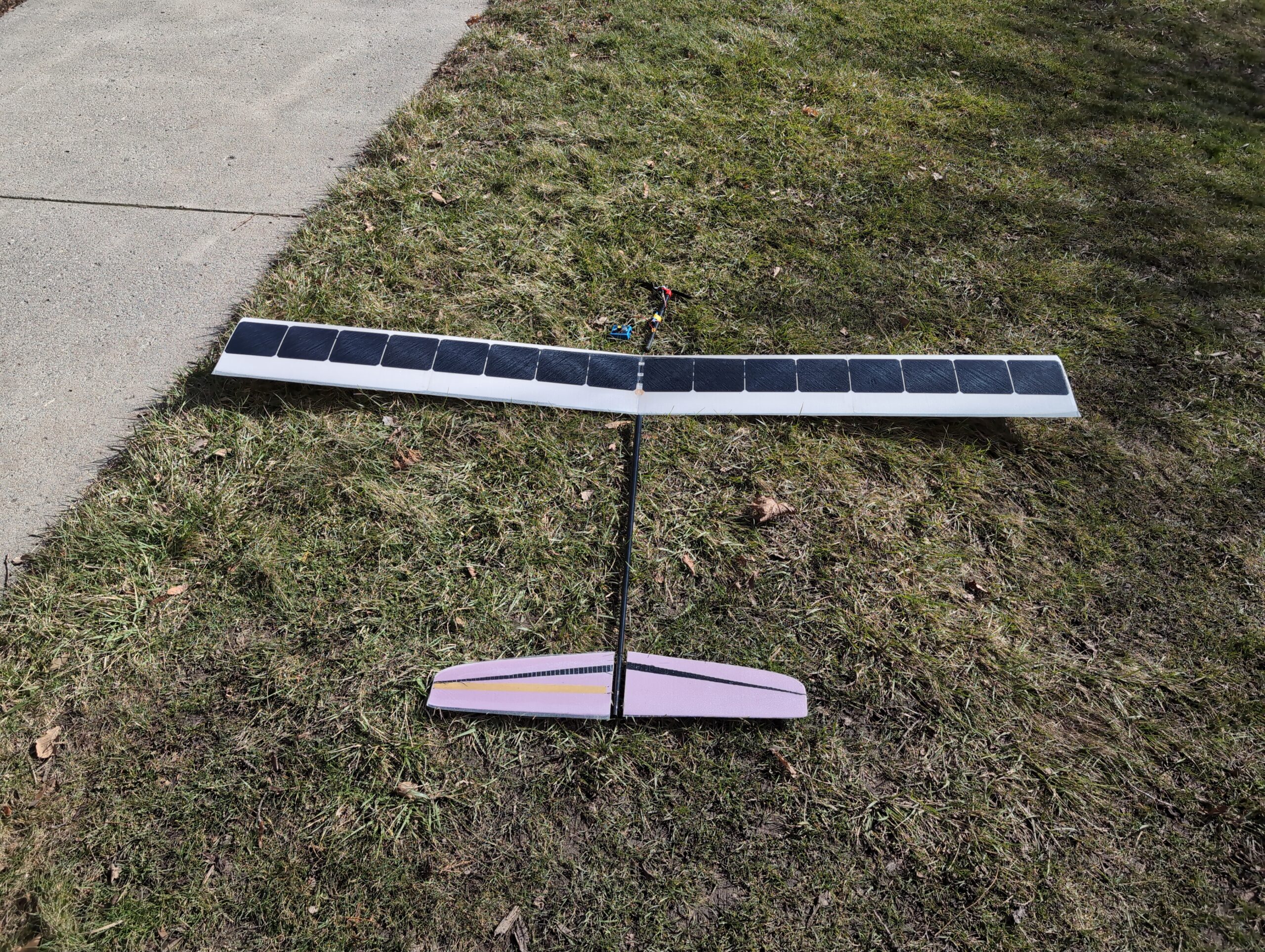
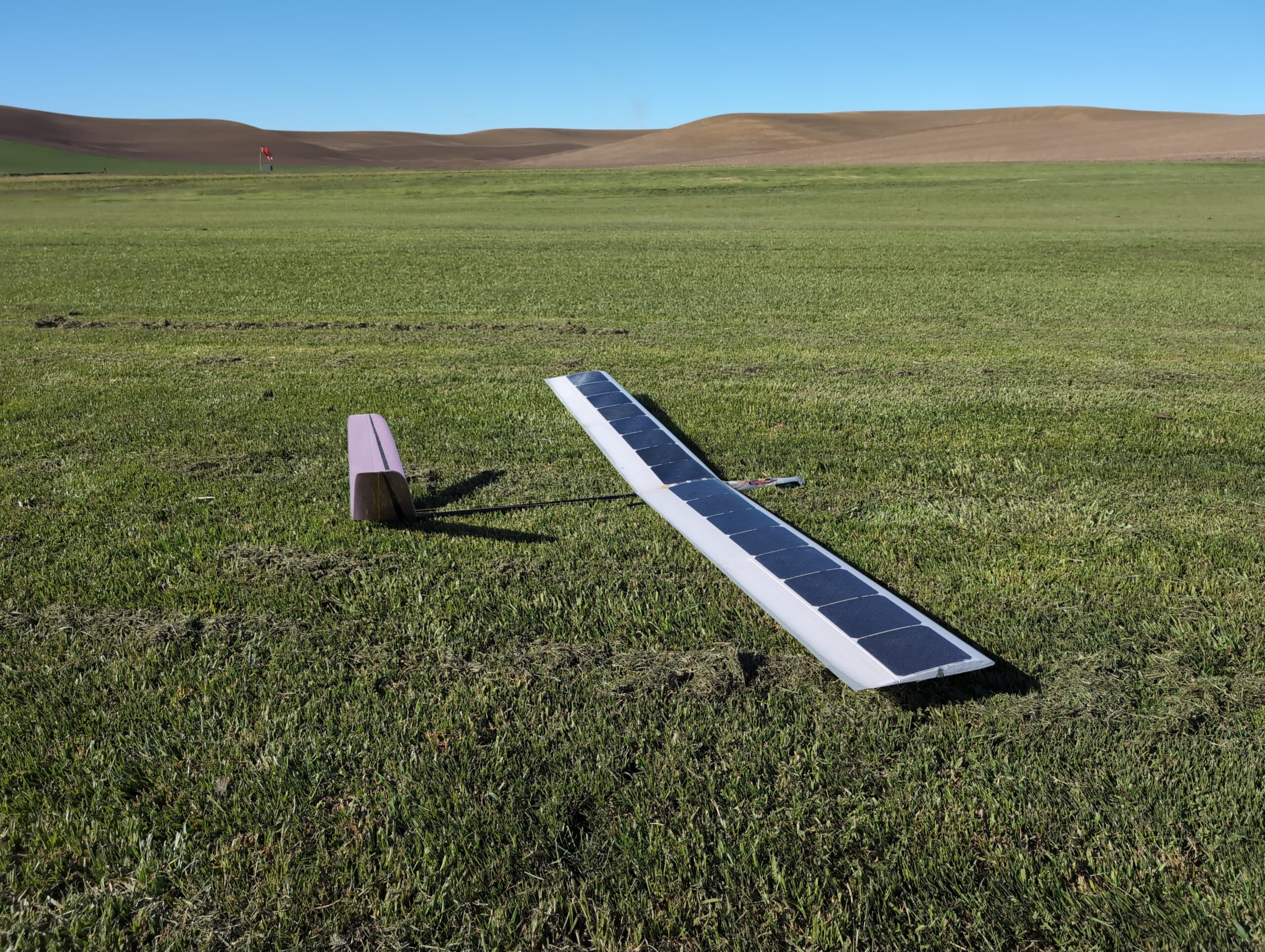
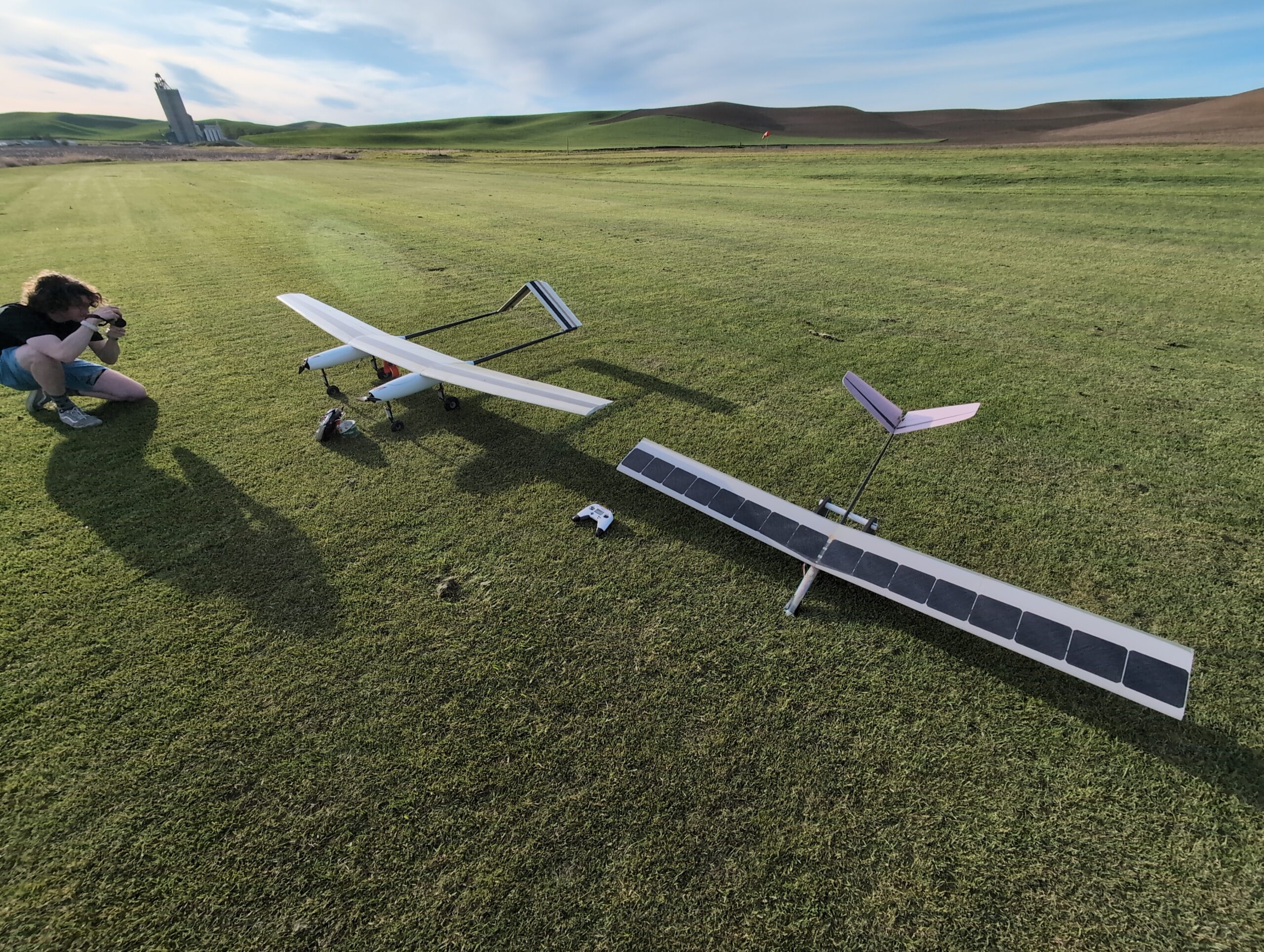
The design for the plane began during the Fall semester of 2023. The tail was built in the Fall and the wing was completed halfway through the Spring semester. The fuselage was molded in late March 2024 which allowed us to begin assembling the parts and installing the electronics. The plane had its maiden flight on April 22nd which went successfully. After a few more flights later that week to test out the autopilot and telemetry we attempted an endurance flight beginning at 9 am on April 27th. The flight ultimately had to be scrubbed due to rain but the plane managed to fly for almost 4 hours with roughly 50% cloud cover and around 10 mph winds which suggested that the plane would be able to fly nearly all day if the weather was favorable. On the last day of finals week, May 3rd we attempted another endurance flight, this time successfully. The plane flew for a total of 9 hours and 5 minutes, starting at 9:10 am and ending at 6:15 pm. Lastly, on June 20th one of our members flew the solar plane for 11 hours and 40 minutes, starting just after 7:30 in the morning. It averaged a power draw of 19.7 watts and flew with an airspeed of just under 9 m/s in a 100 m diameter circle below 400 ft in the air. Throughout the flight, it traveled 228 km over the ground!
If you have any questions or comments about the plane please post to our RCGroups thread.
Design
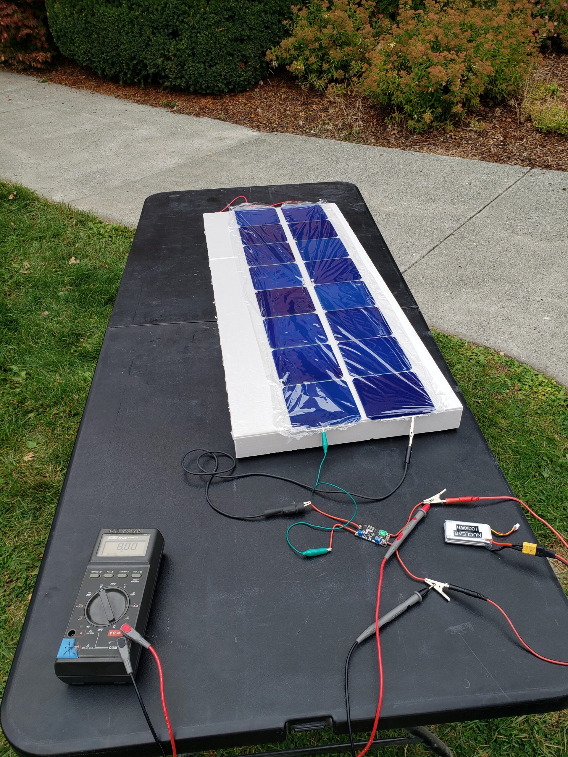
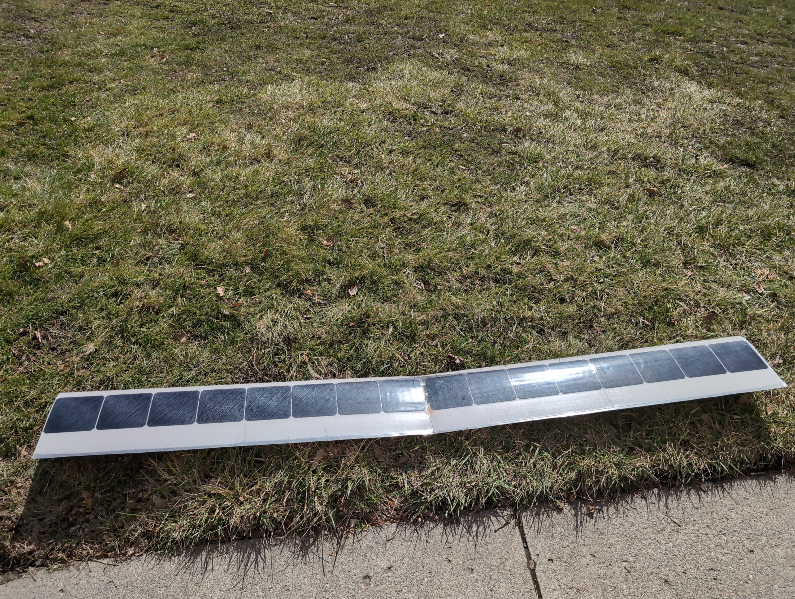
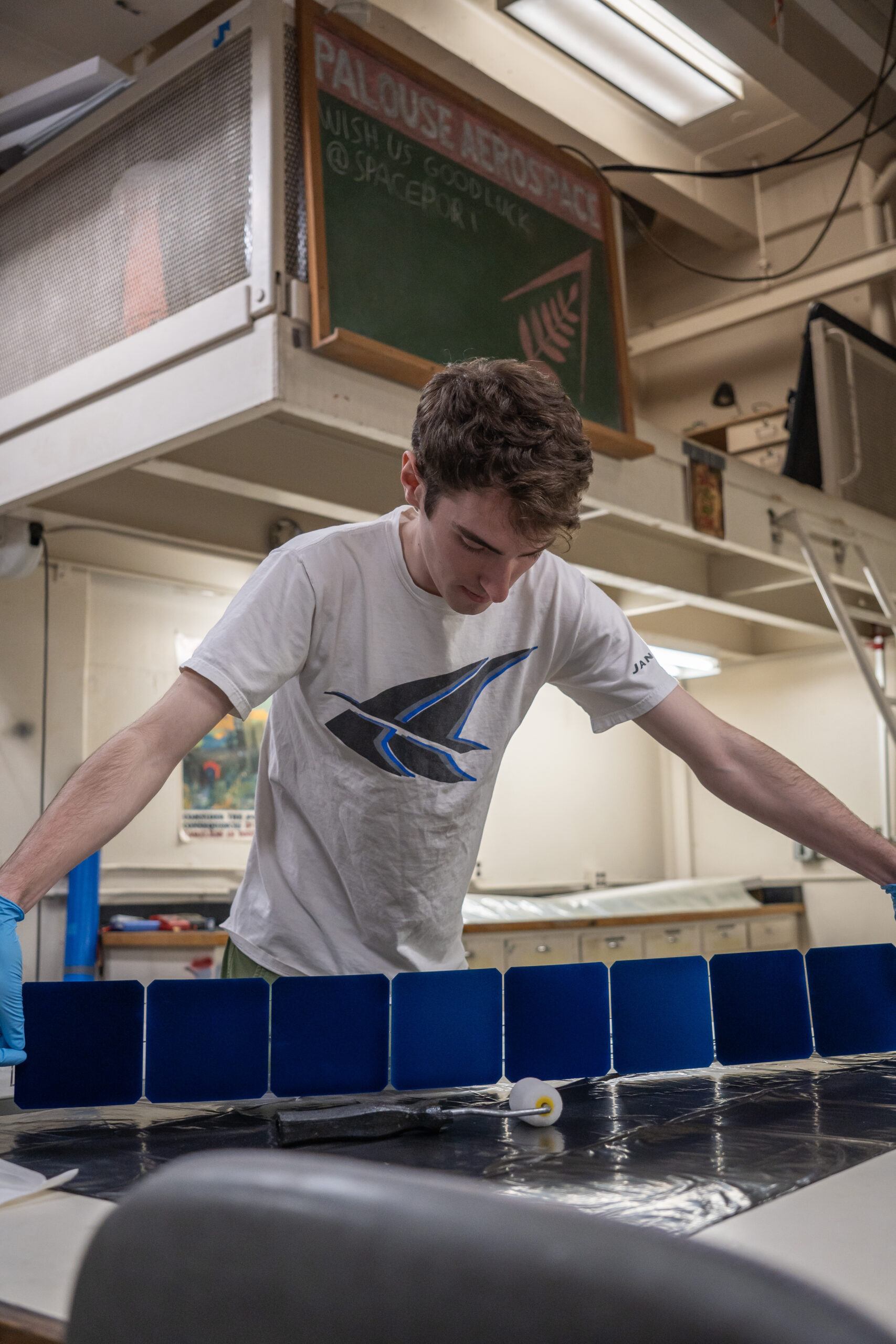
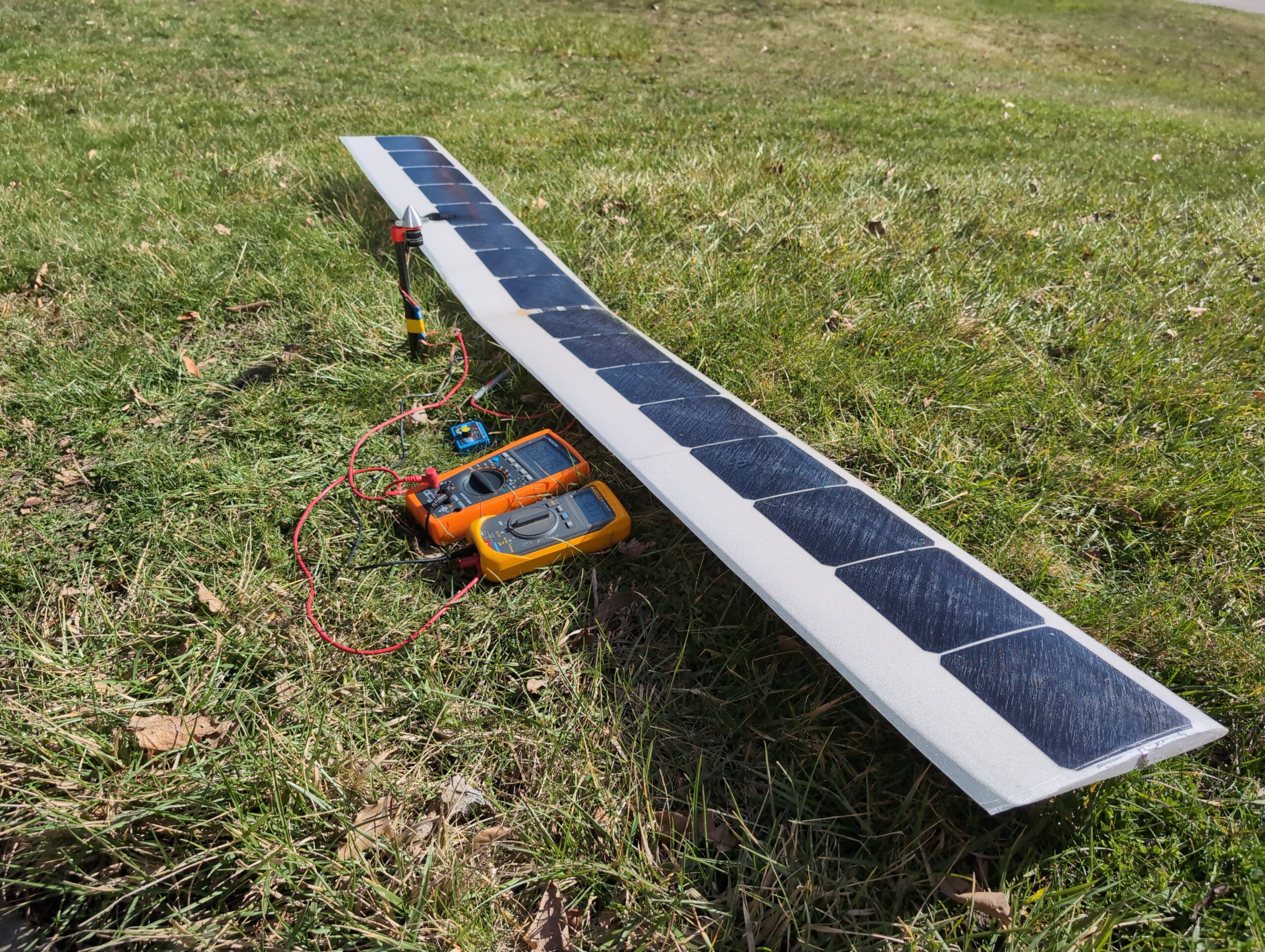
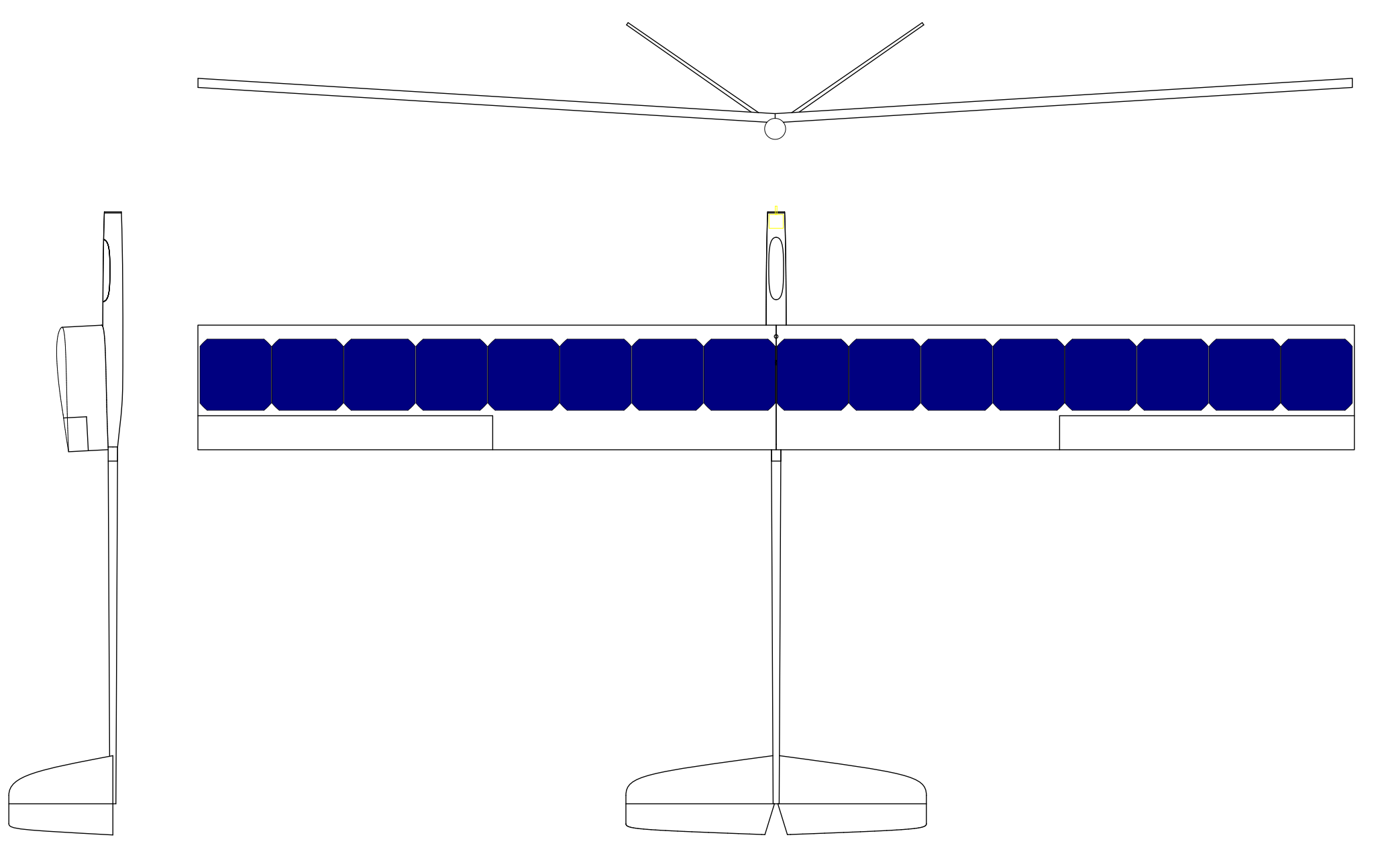
The design of the plane is centered around the solar cells. The wing is a simple constant cord 2 meter wingspan. There are 16 Sunpower C60 solar cells in series to give us between 8 and 9 volts at our maximum power point (MPPT). The solar cells are nominally rated to generate 3.4 W at 1000 W/m^2 of solar irradiance. To get a realistic estimate of solar power we utilized solar irradiance data collected by NOAA in Seattle. Using this data we were able to calculate the average solar irradiance during the time of year we would fly it and at the time of day that we would be out. Then we estimated the various inefficiencies in our system. Through environmental tests and real-world tests of the various components, we will be able to reverse the calculations to find the real inefficiencies in each component. The only exception to this is that it is very difficult to estimate the penalty due to encapsulation because we would need either a very bright light or a way to measure the solar irradiance on a given day.
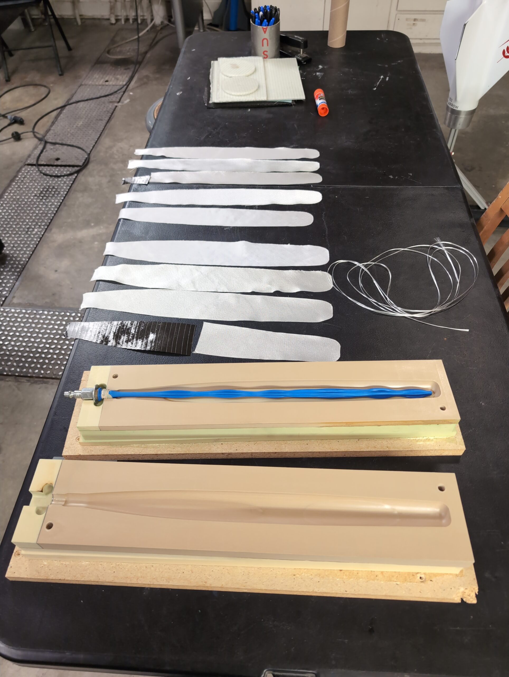
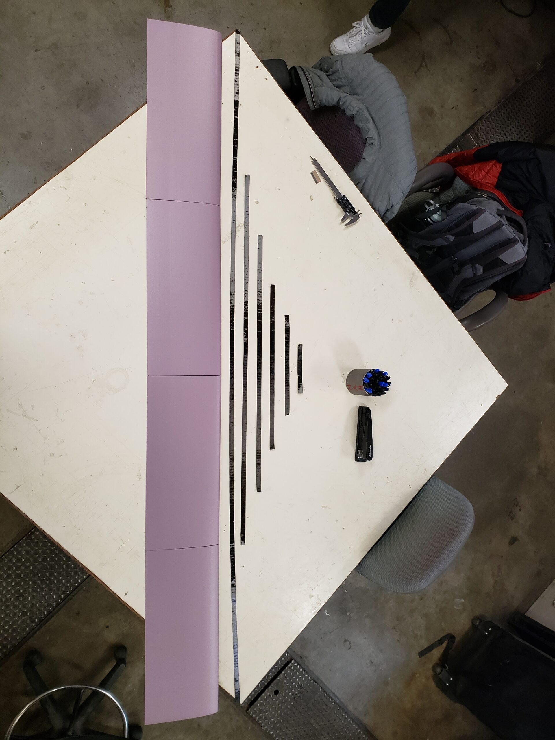
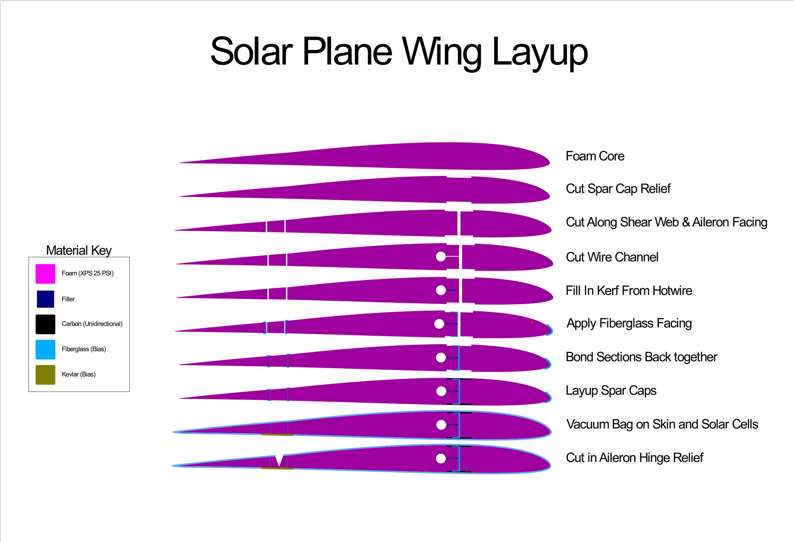
We originally had designed the wing with a rather complex structure involving many steps. The image below shows the process of building up the structure but omits the wiring and the solar cells that go under the fiberglass skin. We struggled with maintaining the airfoil geometry and eventually scrapped the wing before applying the solar cells and top skin. Our spar sizing calculations showed that we could remove the fiberglass shear web without increasing the wing deflection significantly. This combined with holding the thickness of the spar constant and instead tapering the width ended up simplifying the spar design substantially which made the wing far easier to build.
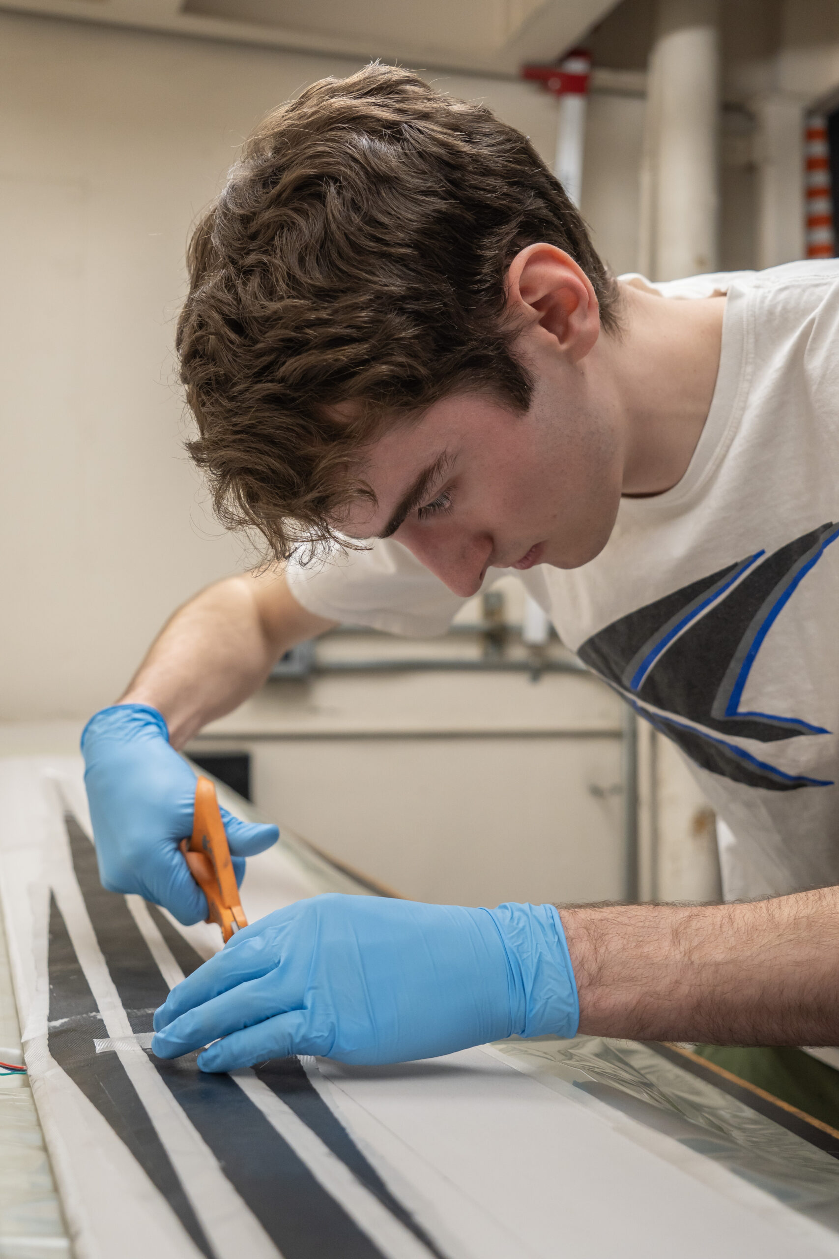
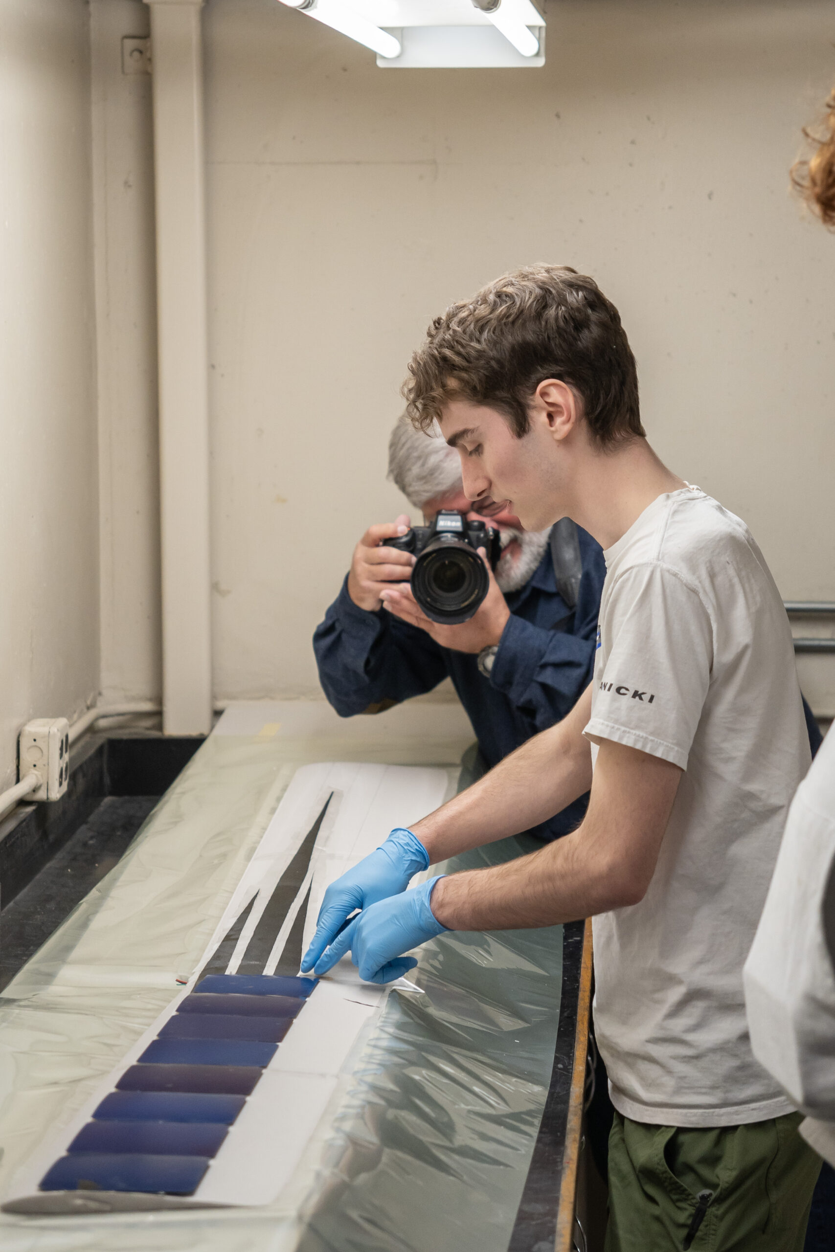
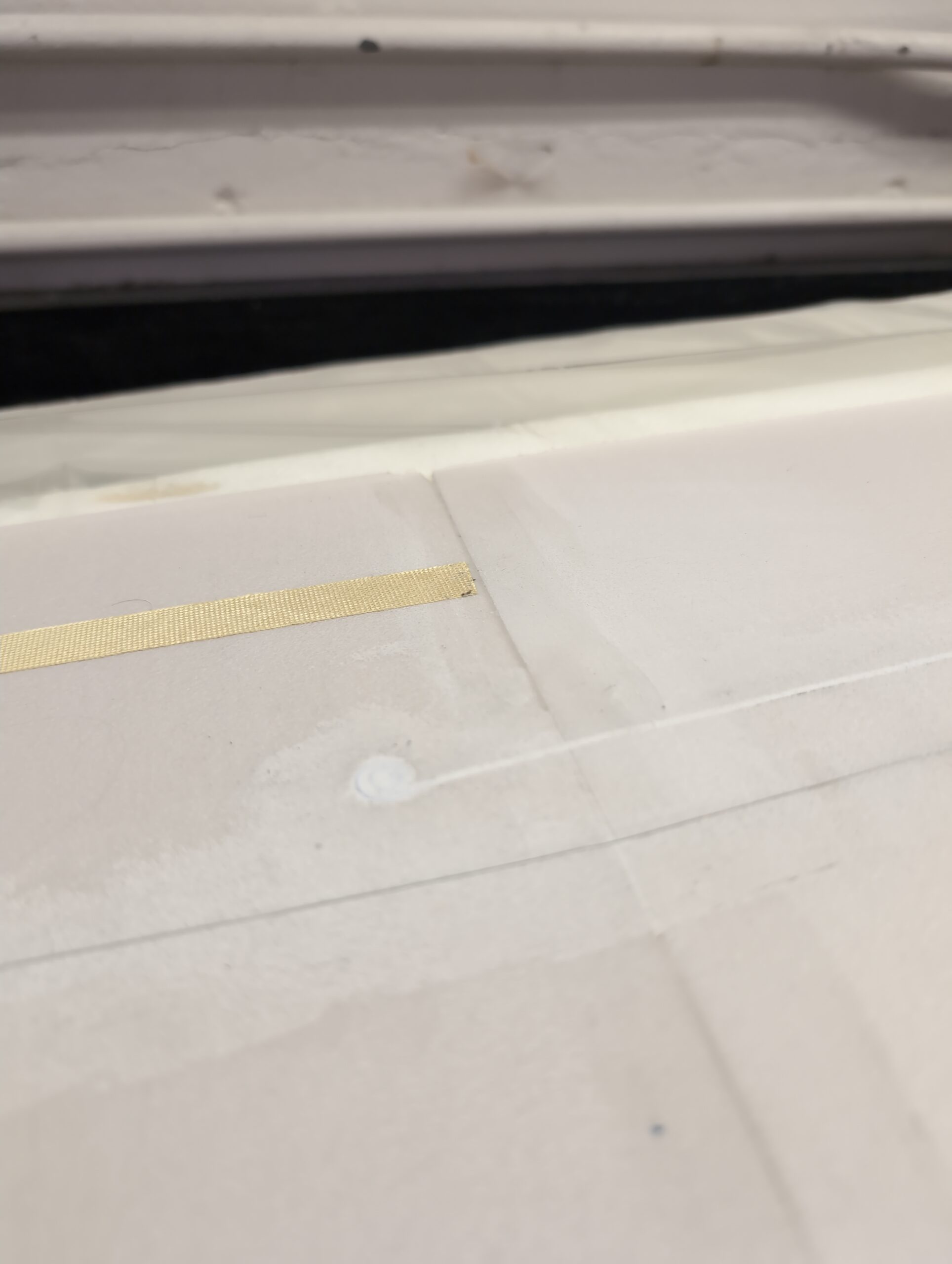
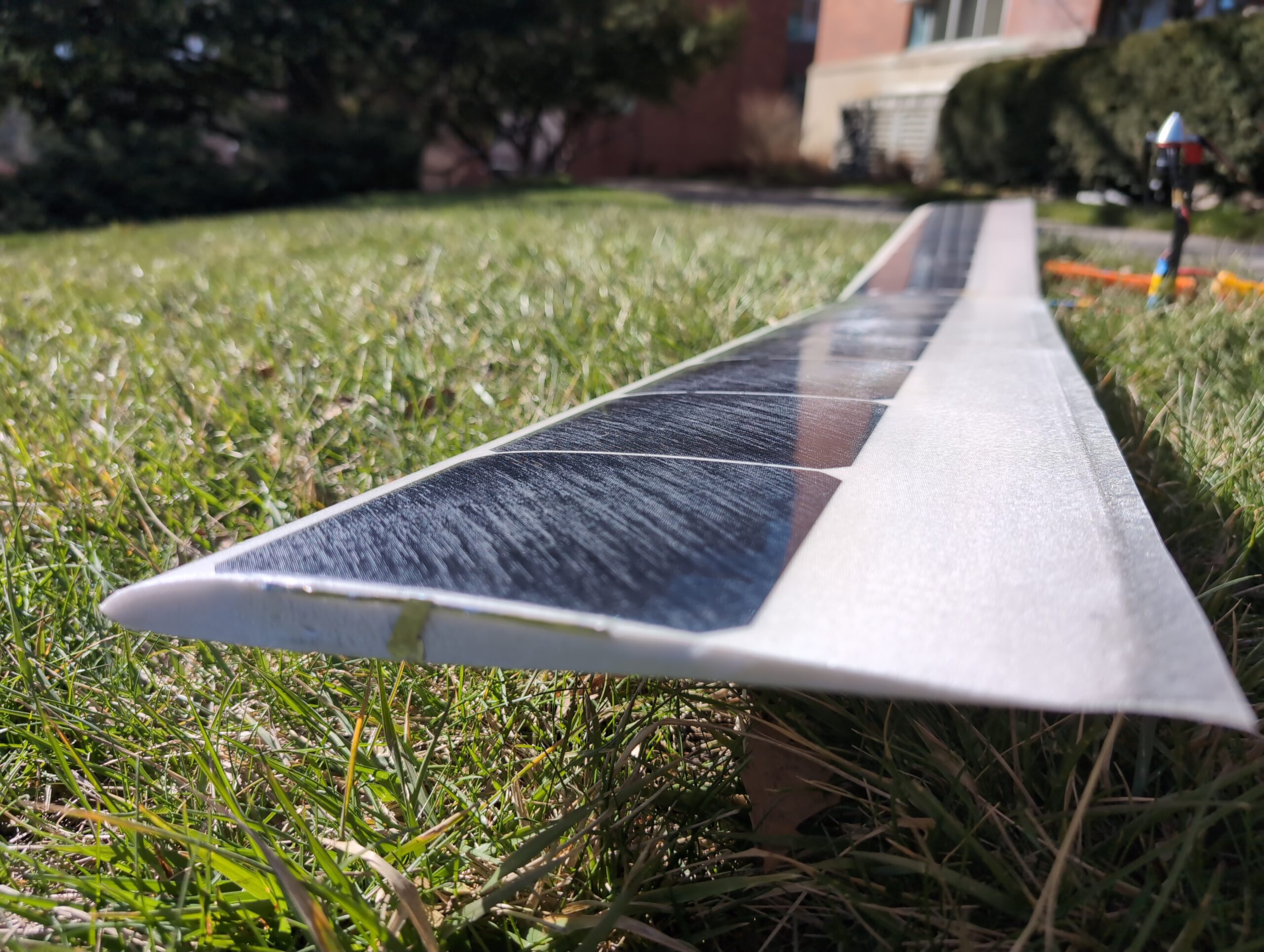
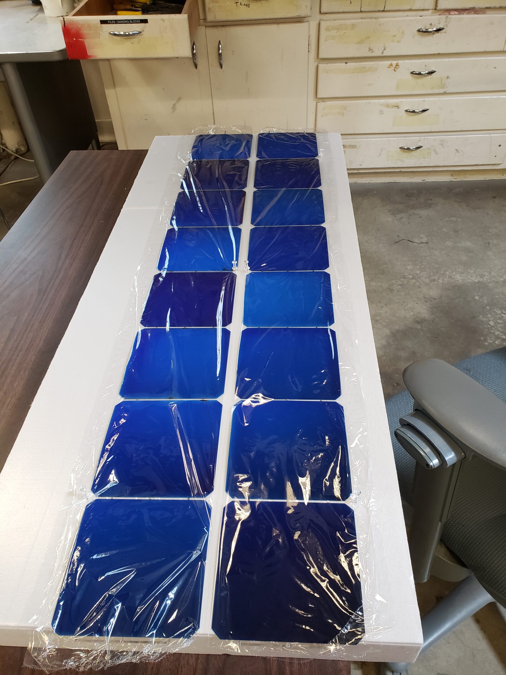
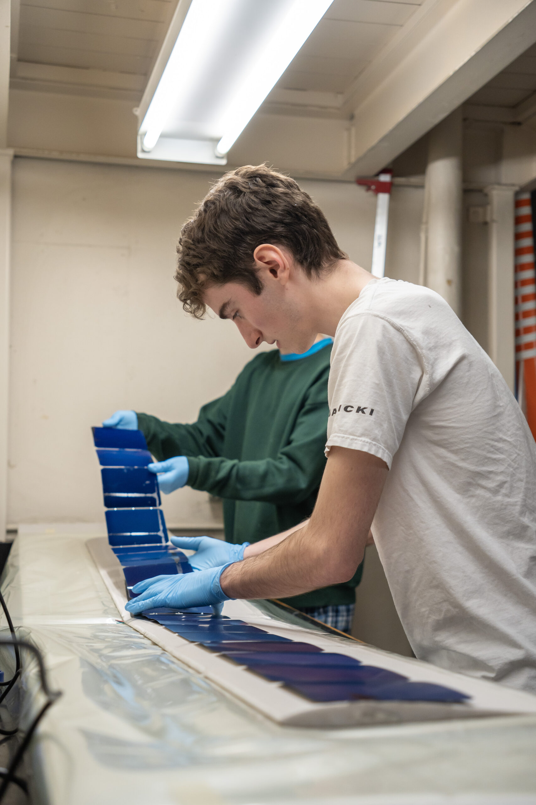
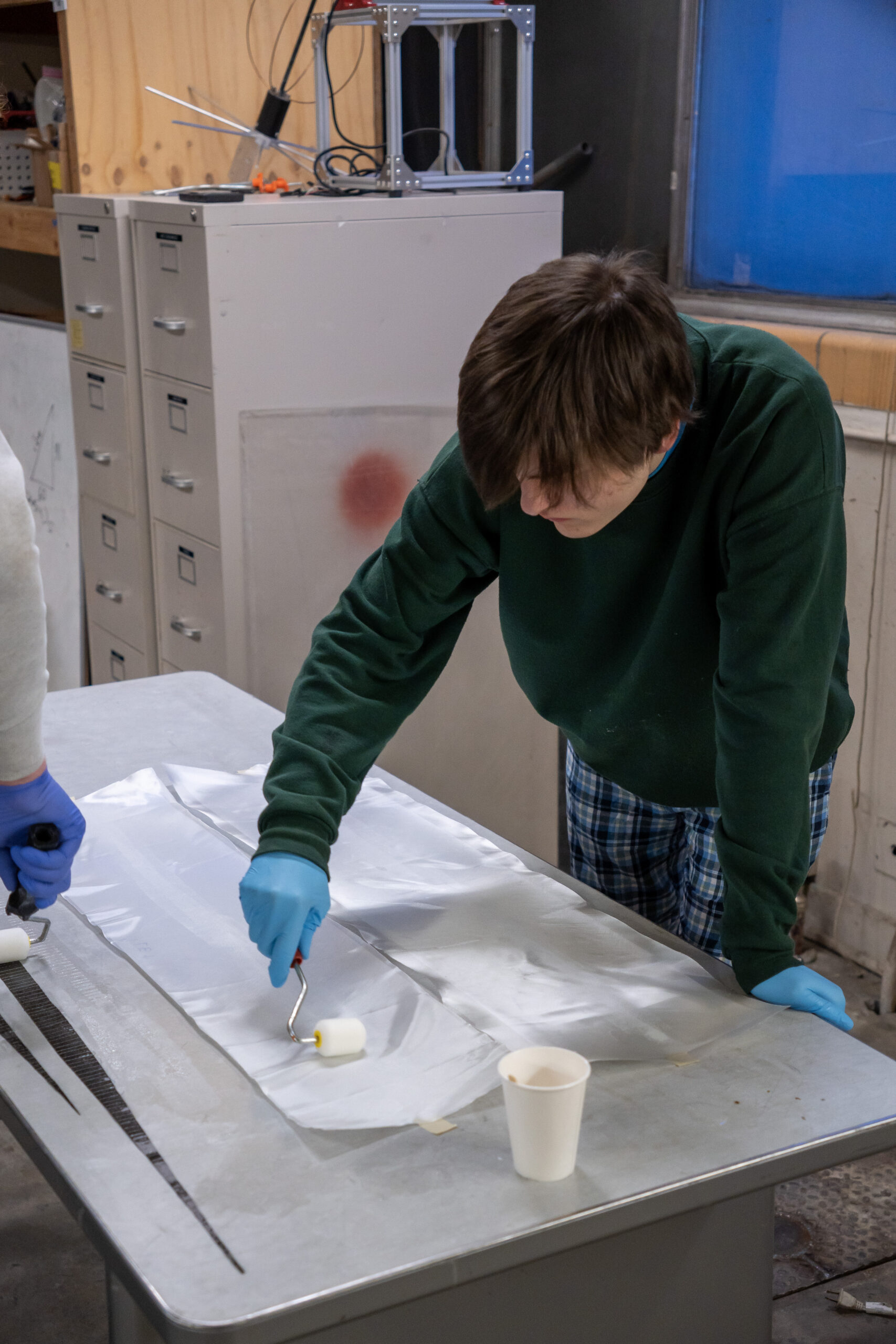
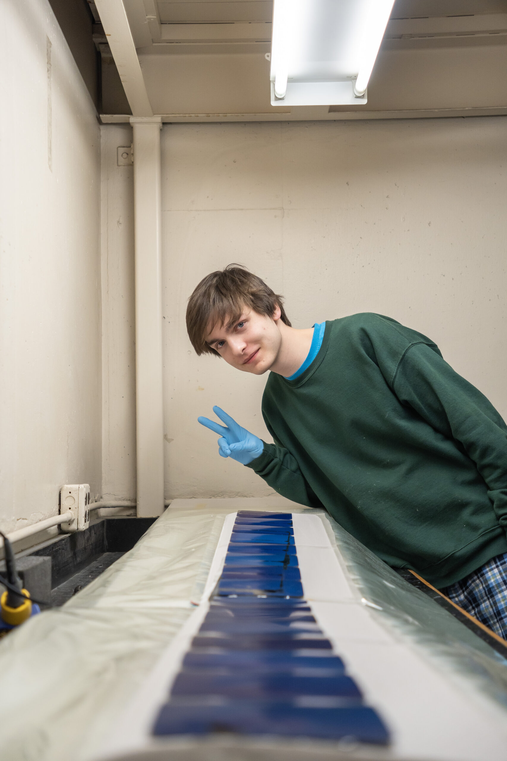
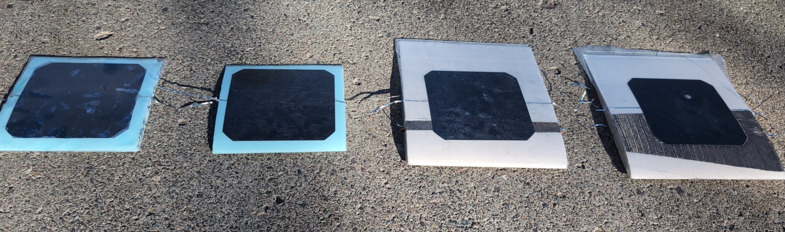
A series of solar cell test laminations informed the encapsulation method. The solar cells are surprisingly flexible and durable. They can be cracked and still operate without a noticeable decrease in efficiency. This makes them excellent candidates for placing under the fiberglass skin and above the foam core of a vacuum-bagged wing. The pressure of the atmosphere while in the vacuum bag presses the cell into the foam and reduces the bump on the surface of the wing to roughly 3 or 4 thou. Unfortunately, the maylar release film used on the surface of the wing traps some air above the cells and causes a slight white discoloration on the surface. The biggest challenge is that the bottom of the cells are covered in copper traces which will short out if they come in contact with the carbon of the spar. This can be countered by placing the cells behind the spar (like with a D box spar) or isolating the carbon by placing a lightweight fiberglass fabric between the cells and the spar.
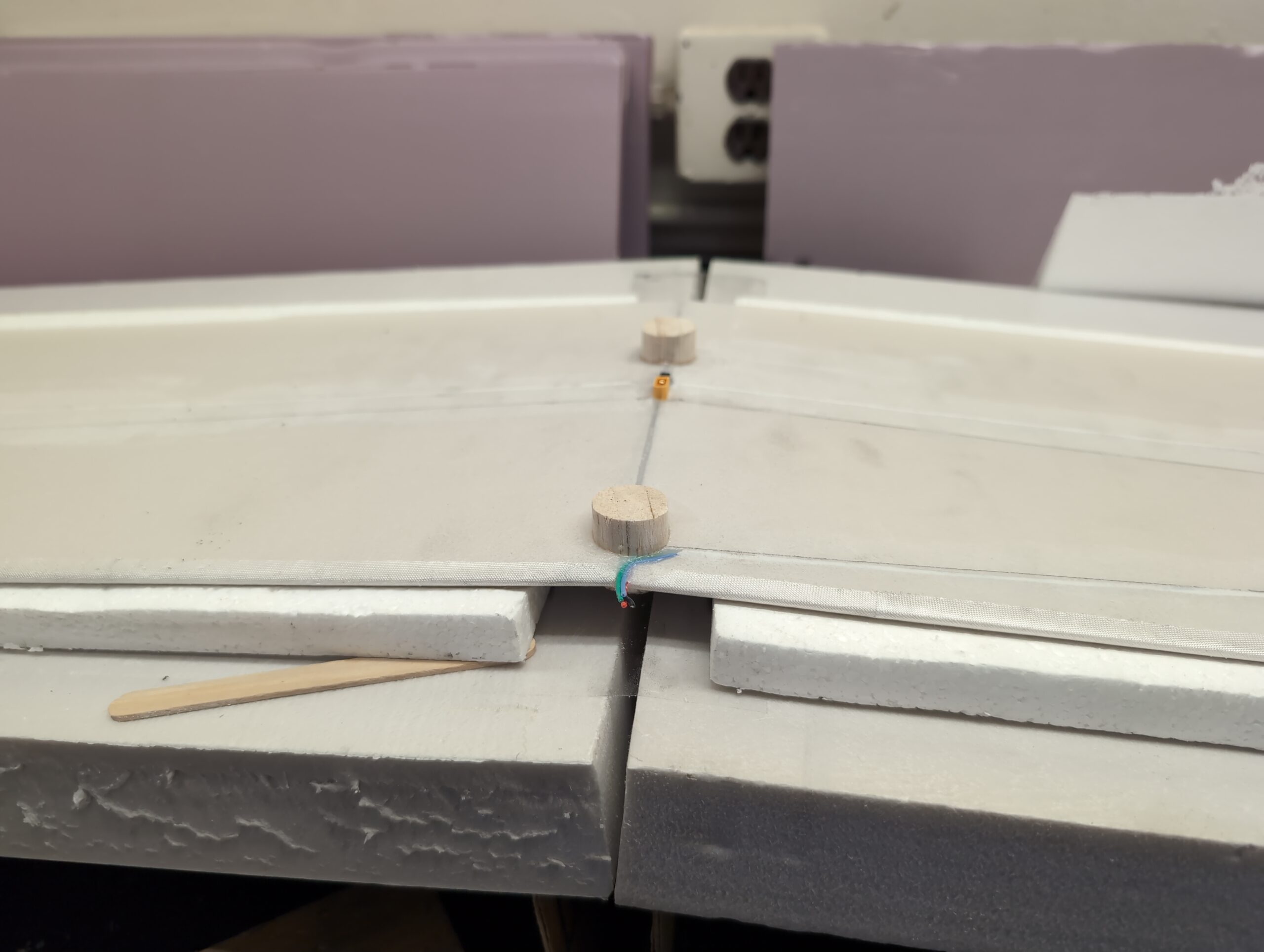
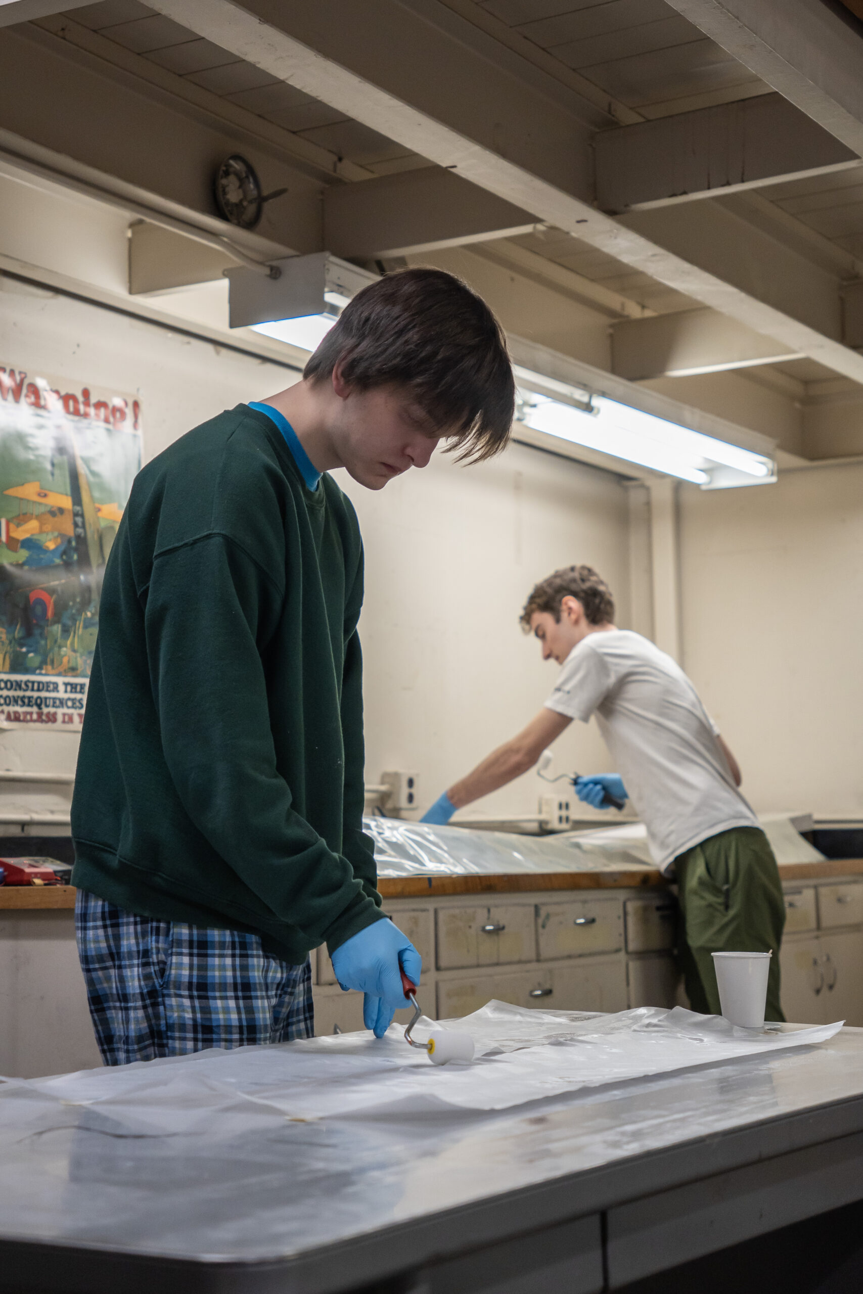
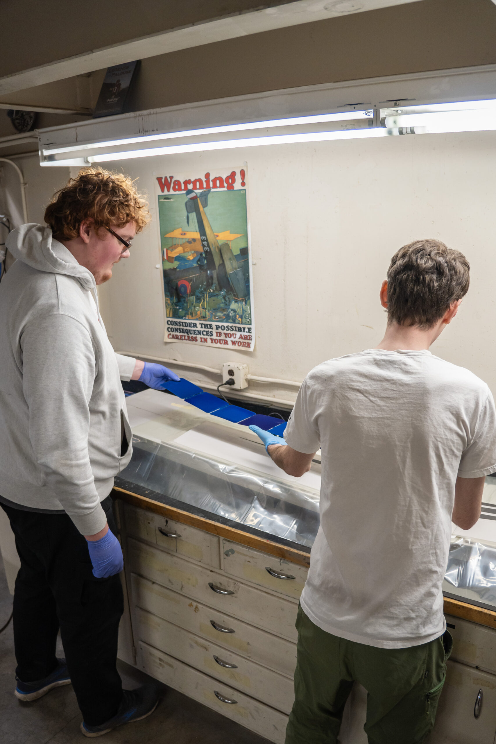
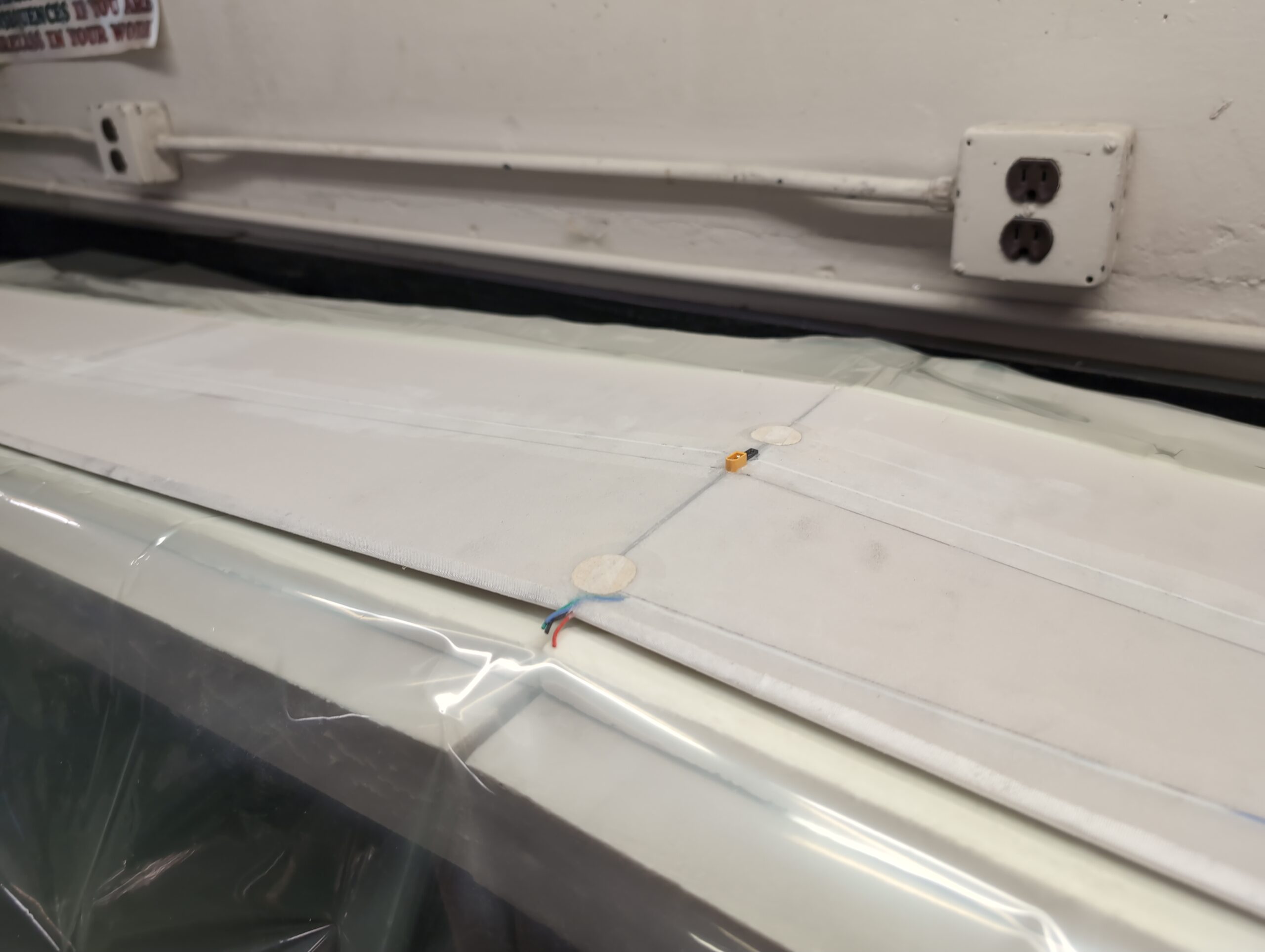
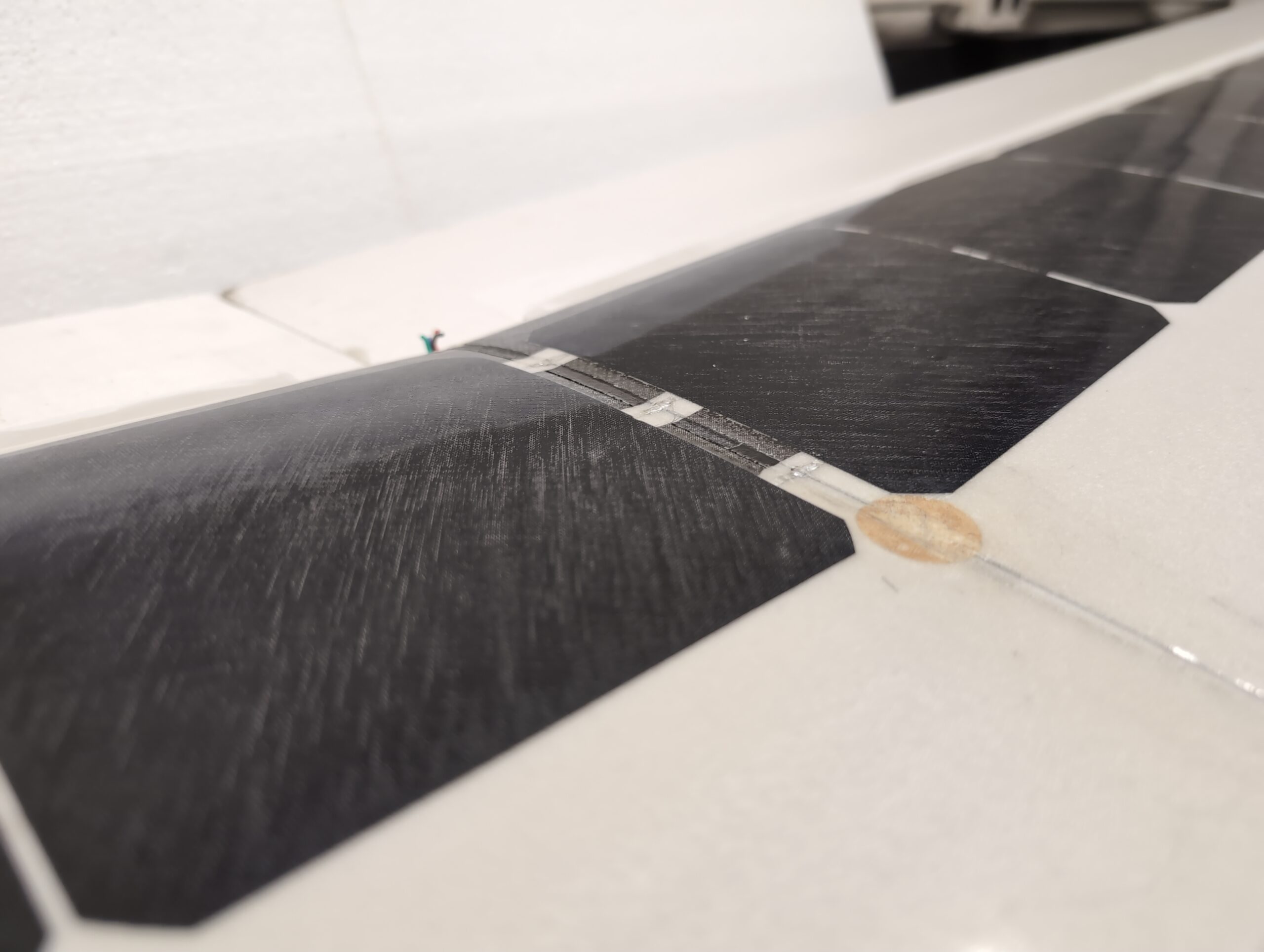
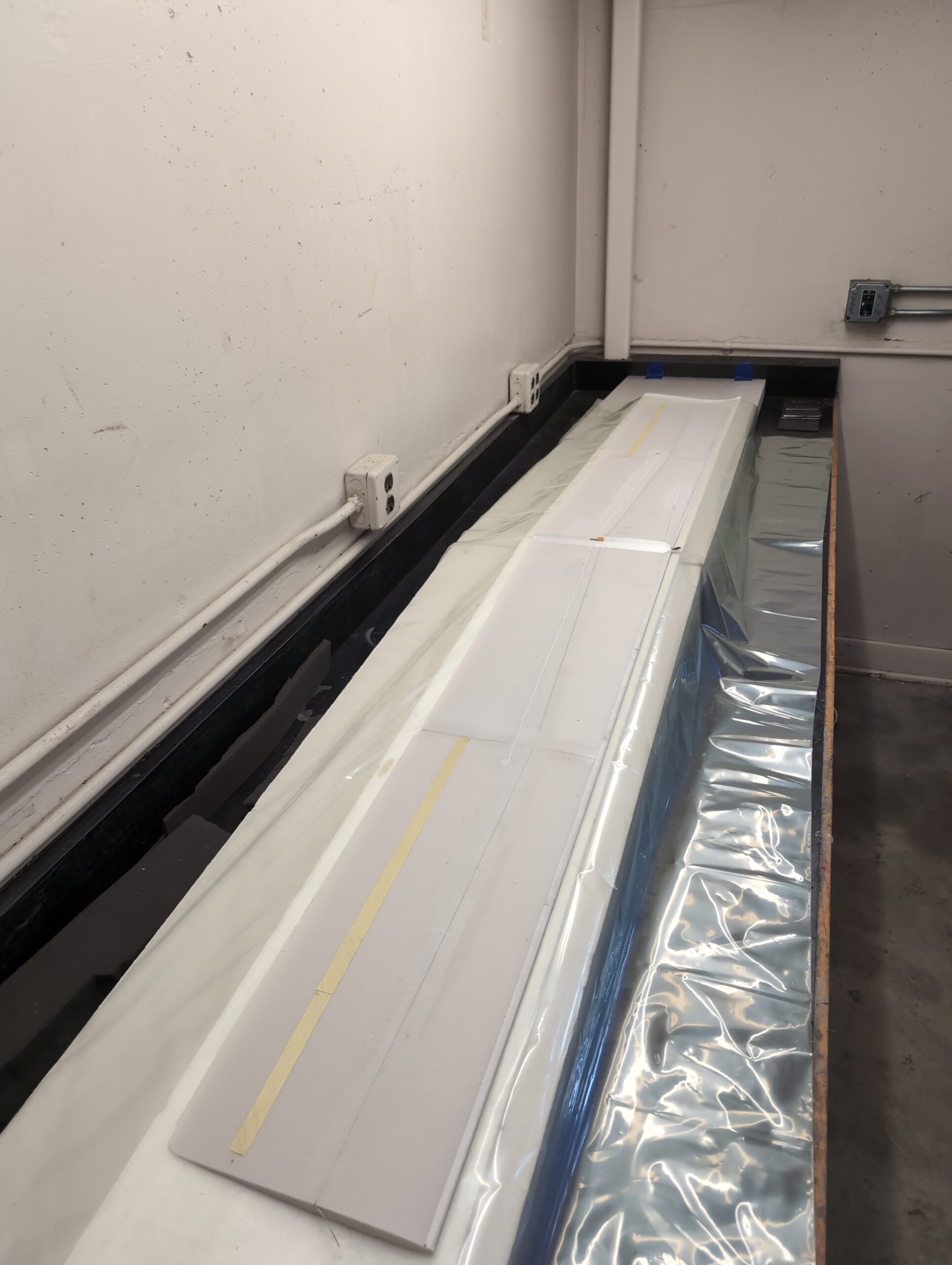
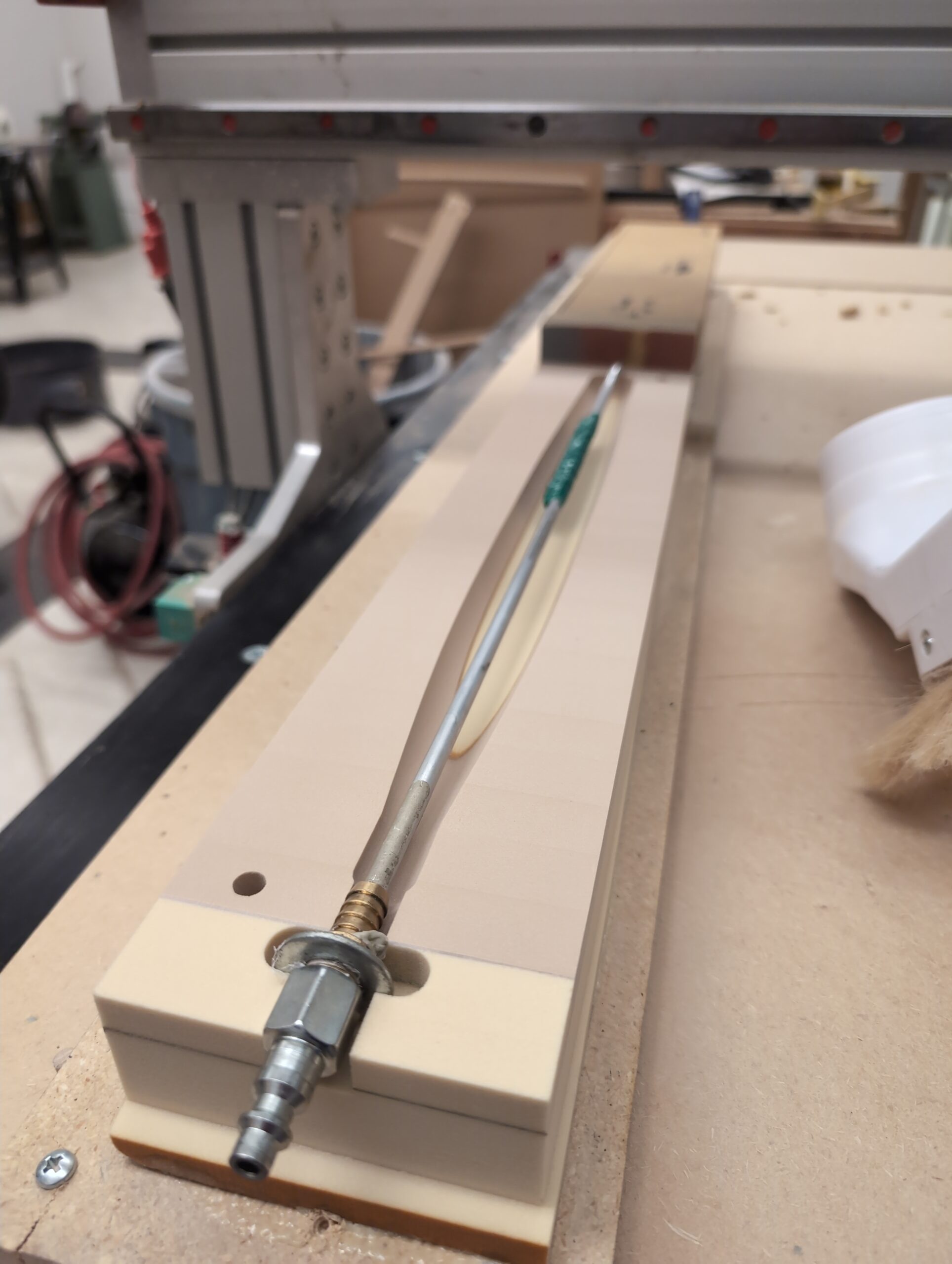
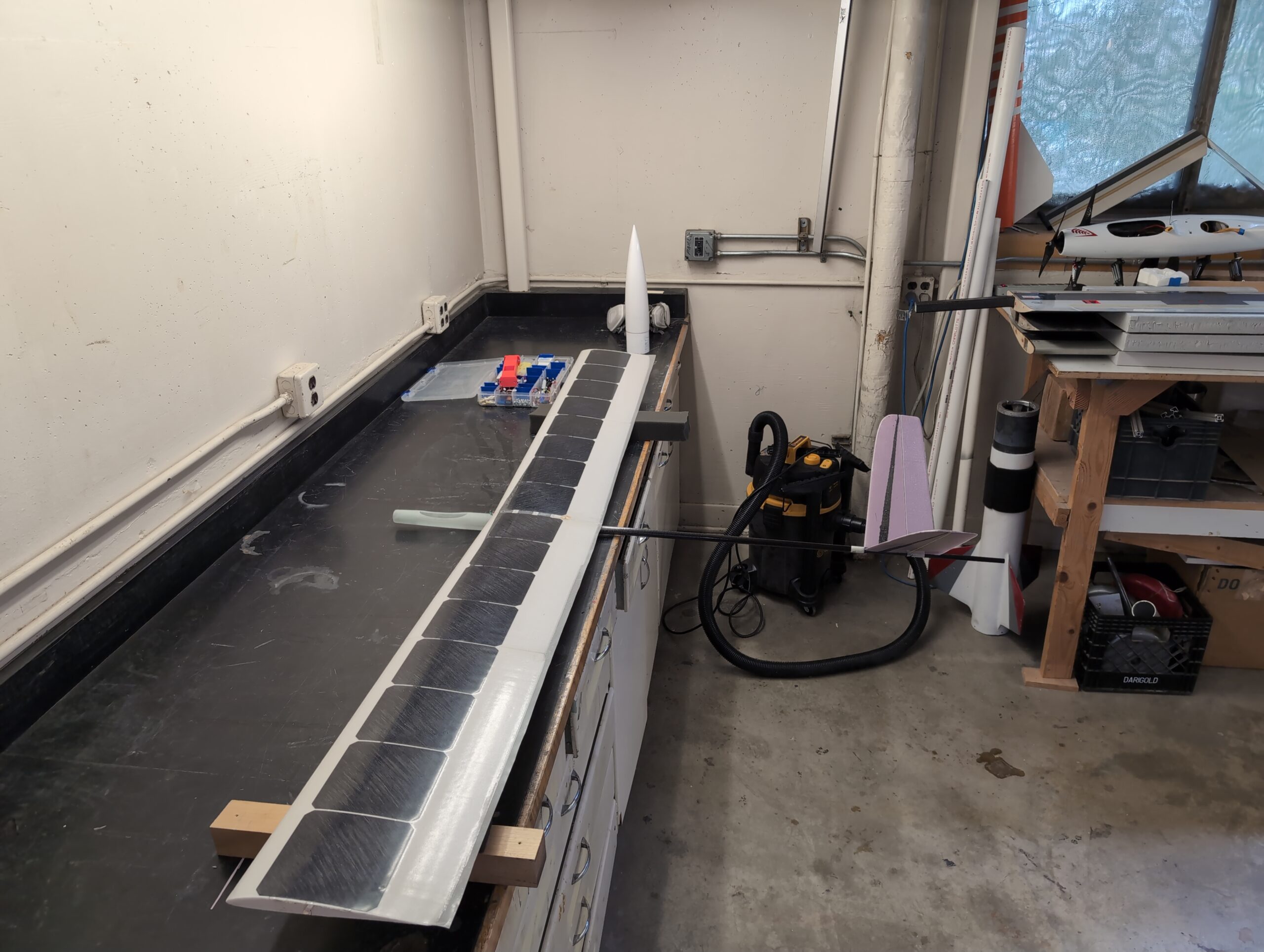
The wing was vacuum bagged as a single piece to simplify the solar cell connection at the dihedral inflection point. This also reduces weight and makes for a stronger wing. To bag it with the dihedral angle required a custom surface to match. This was made with excess XPS foam insulation and cardboard ribs glued to the table.
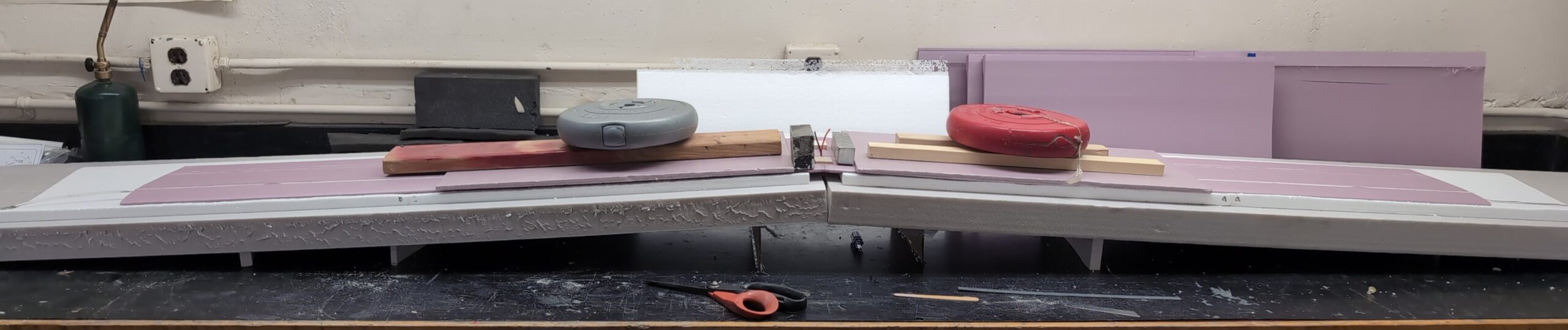
The spar on the top of the wing was split into three sections to allow the soldered tin connections to compress into the wing without the resistance of the carbon fiber. This was likely unnecessary but was a safer bet. More testing will be done in the future to better inform any future solar wings.