Washington State University Aerospace Club
Casey Adam Doan, Aerospace Club President
Noah Thompson, Rocket Team Lead
Bryson Jaipean, Rocket Team Vice-Lead
A preliminary design report submitted on January 18th, 2019
Executive Summary
The aerospace club was created to provide students at Washington State University opportunities to develop practical experience and promote collaboration in a multi-discipline engineering team.
The goal for this year is to design and launch a high-powered rocket carrying both an egg payload and a Doppler-effect based velocity measurement device to 10k ft this June as participants in Spaceport America Cup 2019. The project objectives include
- Design a centrifuge for large volume egg testing and a custom stability simulation based on MATLAB and SolidWorks.
- Create an egg-support structure with neutral buoyancy suspension of the egg aided by a 3D-printed, elastic mesh.
- Design and construct a rocket that could deliver both packages to a targeted altitude and safely recover it.
Background
Spaceport America Cup (previously IREC) is an international collegiate sounding rocket competition with over 100 participant teams from all over the world. With a significant scoring emphasis on team dynamics and engineering exhibition, this event serves as an excellent platform to empower and educate our club’s members. The caliber of technology produced for this competition increases every year. Last year, the club launched an L-class motor rocket carry a 3U CubeSat. Unfortunately, due to an unforeseeable circumstance, the custom navigation system on board failed and resulted in the loss of the rocket.
This year WSU Aerospace Club is pushing hard to transition into a more capable, competitive team. In order to achieve this objective, we are using this year’s rocket as a platform to introduce our members to more difficult testing techniques and facilitate the development of custom stability and trajectory simulations. Having learned from the failures of previous years, we are also taking advantage of a newly renewed enthusiasm for rocketry to strengthen our club’s structure and institutionalize the transfer of knowledge from one year to the next. In the following months, we will finalize the design of and begin construction on a high powered rocket for entry into Spaceport America Cup 2019. It will carry both a raw egg payload and a siren which will be used to measure velocity during boost using the Doppler effect.
In order to perform the high volume of testing necessary to properly design an egg support structure (and quantify egg strength), we are designing a centrifuge capable of spinning a 1kg payload up to 23g’s of centrifugal acceleration. Additionally, the Doppler payload requires that there be sound ventilation in the body of the rocket. These small additions, having been determined to invalidate commonly used rocket design platforms, pushes us to develop our own stability and trajectory simulation models.
Overarching Rocket Design Criteria
- Basic criteria (imposed by competition):
- Reach an altitude as close to 10k ft as possible
- Carry at least 8.8lb of payload
- Utilize a commercial propulsion system
- Payload Based Criteria:
- Minimize acceleration experienced (for egg structure)
- Minimize design introduced probability of flight failure
- Remain in Subsonic Flight (for doppler structure)
- Minimize aerodynamic effect of strange external geometries
- Maximize audibility of Doppler siren
- Minimize Cost
Weight is, of course, always a consideration in rocketry. Because early designs use a surplus of propulsive power in conjunction with higher than usual weight to keep acceleration low, it is not listed with the other core requirements above. More specific rocket criteria were omitted here for the sake of redundancy, instead discussed in the design section of this report.
Centrifuge Design Criteria
The design criteria for our centrifuge testing apparatus are:
- Safety
- Apparatus must be of robust construction
- Must fail safe where possible
- Must be remotely controlled
- Must be transportable (for testing away from populated areas)
- Catastrophic Failure of Device must be contained or directed in some way.
- Payload bay must be sealed to fluids, able to withstand sudden dislocation of weight.
- Consistency & Repeatability of Applied Acceleration
- Roughly equivalent acceleration must be applied to all points of payload
- Multiple trials must have approximately same acceleration (repeatable application)
- Power Supplied to Payload & Data Transmission
- The payload must have some form of power supply to the payload bay to support measurement devices.
- Resulting from the need to be remotely controlled, any data collected by the arm must also be stored onboard or transmitted to a ground station at remote control location.
- Versatility
- To maximize the value of this expenditure to the club, we would want to design this device in such a way that other payloads could be tested with it.
- As Always, Minimum Expense Meeting Other Requirements
Current Status of Project
1/ Overall Design
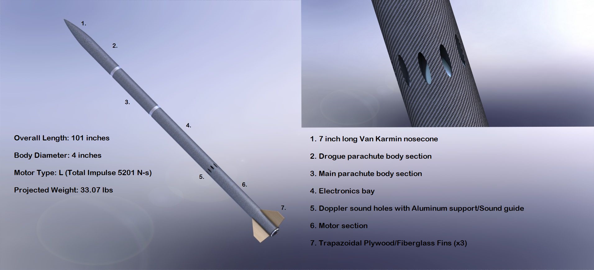
Though specific external dimensions of the rocket itself are in flux, pending the completion of all internal structures, the approximate length of the rocket will be 100in. The layout of the rocket will be, from fore to aft: nose, drogue parachute, ejection coupler, main parachute, rigid coupler, egg payload bay, electronics bay, Doppler speaker, Doppler vent support structure, motor, tail.
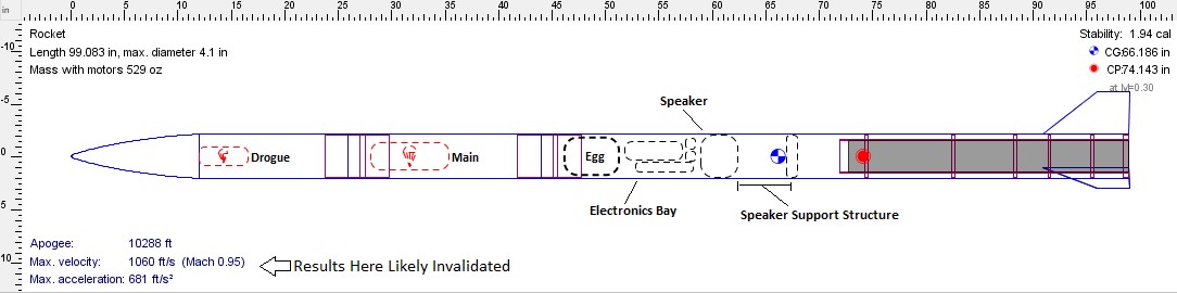
Figure 1. An approximate model of Rocket, made in OpenRocket
We have selected, based on previous experience, the following ejection sequence:
- E-bay triggers drogue ejection, which is primarily driven by the momentum of separating sections (as opposed to the force from ejection charge detonation).
- The aft drogue shock cord will be connected to the lower section by an eye-bolt anchored between the coupler charge wells in a 0.5” bulkhead. The fore drogue shock cord will be attached to the coupler section by an eye-bolt anchored between the charge wells.
- At this point the wiring through the main shock cord has not held an applied load, so risk of flight critical failure of those wires are relatively low. They only need to maintain contact until drogue deployment, after which failure has no effect on flight or data collection.
- E-bay triggers the main ejection
- Wiring failure here after ejection does not affect flight performance.
2/ Points of Concern
Main Parachute Connection:
The main chute connection was an immediate point of concern when considering this layout. Usually, the heavier lower section of the rocket is attached to the main chute by a bolt directly into the motor casing forward closure. To ensure that a coupler might be a sufficient replacement for normal attachment, a baseline static study was performed:
Historically, we have used plywood as bulkhead material where possible to save cost. Our preliminary model reflects this design choice. The material applied here is a custom defined generic plywood, with material properties in a direction normal to the surface. This cannot be assumed to give conclusive or accurate numerical values for stresses, but sufficiently functions as an early verification.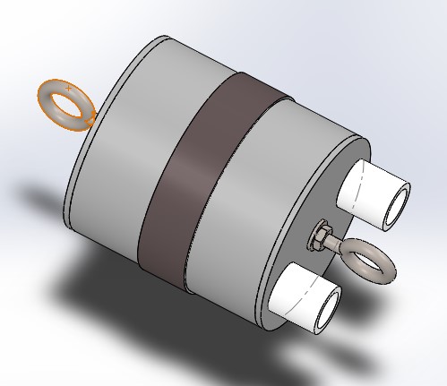
Figure 2. Setup & Materials for bulkhead static study.
The coupler end itself is made of ¼ inch plywood, with a lip cut around the edge (making lip thickness of 1/8th inch).
Threaded rods will insert through coupler, with external bolts on either side bracing against the force of ejection. The closures themselves are also epoxied to the outer edge of the coupler tube. The results of a quick simulation are shown below. The surfaces where bolts on threaded rods make contact are fixed, and the edges which will be epoxied are fixed. This fixture on the threaded rods is not completely accurate, as some translation will be allowed before failure. Because of the direction of applied force, this should still serve as a passable approximation. Curvature based mesh with mesh control around applied load and fixtures is used
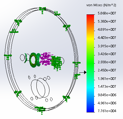
Figure 3. Static study results
As the results to the in Figure 3 illustrate, all parts of the closure except for the concentrations of stress around sharp edges exhibit less than 24 MPa of Von Mises stress, which should be below the tensile strength for most plywood[1] normal to plane. This is with 247 lbs applied to the surface under the rear eye-bolt fixture. At 15k ft above sea level, density of air is 14.96×10^-4 slugs/cf.
Assuming a drogue coefficient of drag of 1.34 (typical main chute drag) and a solid diameter of 4 ft, the force exerted by the chute instantaneously at 140ft/s can be estimated by:
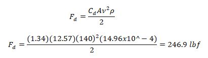 Therefore, for preliminary projected apogee speeds, the use of ¼” plywood as a chute contact should be sufficient. Since it is near failure at stress concentrations, a thicker bulkhead with composite reinforcement will likely be used and verified during design finalization.
Doppler Payload Acoustic Vents:
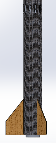
Perhaps the component over our design which commands the most attention is our Doppler acoustic venting section. Sandwiched between the motor and the rest of the rocket, cutting holes in a section which is usually incredibly load bearing reduces the overall strength of the rocket dramatically.
By comparing the CFD produced coefficients of drag at variable velocities for identical rockets with and without the vent structure, we determined that by adding the structure we significantly increased drag as well. We used a one-dimensional trajectory program in MATLAB (taking SolidWorks data as input) written by the previous rocket lead, Sean Journot, to verify that 10k feet were still attainable with the addition of such significant drag. The base equations for this code are simply one-dimensional kinematics equations, substituting values on each iteration for differing atmospheric conditions. Sample code is included in Appendix 1.
To allow for these holes to be cut, we are designing an internal support structure to bear the load of that section. It will be fixed rigidly to the body tube below, between, and above the holes. The internal structure forms a parabolic nosecone shape at its core, being tangent to the body tube at vent exit. The structure is being designed to support both thrust and aerodynamic forces in entirety with a safety factor of four. Our own version of this MATLAB simulation is currently being developed, adding a degree of rotational freedom and horizontal translation. When completed, though very computationally expensive, this simulation should be able to more accurately predict stability and trajectory of any ballistic projectile modellable in SolidWorks.
Figure 4 . Lower section of rocket
3/ Centrifuge Design
The decision to attempt to use a centrifuge for egg testing supplements the usual method of launching test rockets. When considering whether to proceed with designing the proposed centrifuge, the following qualitative comparisons were made.
Table 1. Qualitative comparison of test rockets and centrifuge
| Test Rocket Pros | Test Rocket Cons |
| · Less Expensive Upfront
· Can apply large accelerations for short periods of time · Easier to develop and gain approval · Easy to balance |
· Testing opportunities are infrequent
· Has per launch cost that is quite high (motors are guaranteed expense) · High risk of rocket failure or loss during testing · Applied acceleration cannot be easily fine-tuned · Variation between trials would be larger (dependent on more factors) |
| Centrifuge Pros | Centrifuge Cons |
| · Very low operating cost
· Ability to test on a continuous basis · Lower risk of device failure or loss (money spent is a greater investment) · Opens door to physical acceleration testing of any small structural device · Very high consistency of applied acceleration |
· Need to Develop Safety Protocols and Obtain Approval
· Higher upfront cost · Will require proper balancing · Will not likely be able to apply large accelerations for short periods of time. |
Because of the egg payload, we benefit greatly from the ability to test a large number of eggs with varying structures in different orientations. We plan to examine the responses of different farming methods, weights, sizes, and orientations of eggs under a consistent acceleration to determine those most suitable for launch. Because eggs are so fragile, we also would benefit from the ability to test each possible egg support structure multiple times. We plan to produce a probability distribution of egg failure for each structure considered. The ability to have such a test and revision process, in addition to the return on value in following years with its lower operating cost, leads us to favor the construction of a centrifuge over increasing our use of test rockets.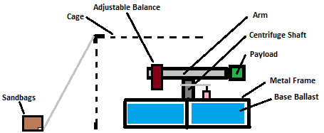 Figure 6. Centrifuge Illustration (not to scale)
The centrifuge arm is selected to be 13 inches in radius. In selection, we wanted a relatively low kinetic energy (easier to contain failure), and relatively low error of applied acceleration (difference in centripetal acceleration over payload). Taking the payload to be 3” in length along the axis of the arm and 25 g’s as the maximum desirable average applied acceleration, the percent error of applied acceleration (using 25g’s as base) can be plotted as a function of centrifuge arm radius. This relationship was used to pick an optimal radius, just below 10% error (deemed an acceptable threshold). Its simple derivation is included in Appendix 2. The remaining centrifuge components are still being modeled but will be completed by mid-February.
The main shaft of the centrifuge will be supported by a thrust bearing and a machine bearing. It will be threaded at the base, with a nut attached during assembly to prevent the shaft from lifting. The arm itself is currently intended to be carbon fiber (its lightweight deemed more beneficial to risk minimization than a more robust but heavier arm). A brushed DC motor will be used to power the shaft, connected by a chain drive.
Centrifuge Electronics
The centrifuge will be controlled by a custom microcontroller with onboard MPU- 6050 accelerometer sensor and strain gauges. The controller will store data on micro SD card as well as relay real-time stream of data to nearby electronic devices via a Wi-Fi access point. The centrifuge will also be equipped with a safety feature to analyze and detect any odd behaviors, and immediately shut down the centrifuge.
An application to control the centrifuge is also in an early stage of development to help multiple electronic devices to establish a 2 ways communication with the centrifuge. The apps will allows the device to obtain data from the centrifuge, and have full control of the centrifuge. User will be able to change centrifuge rotational velocity, turn on and shutdown the machine from a safe distance. Currently the centrifuge could transmit data to a mobile device with a range up to 200ft. This allows users to establish a safety radius of operation
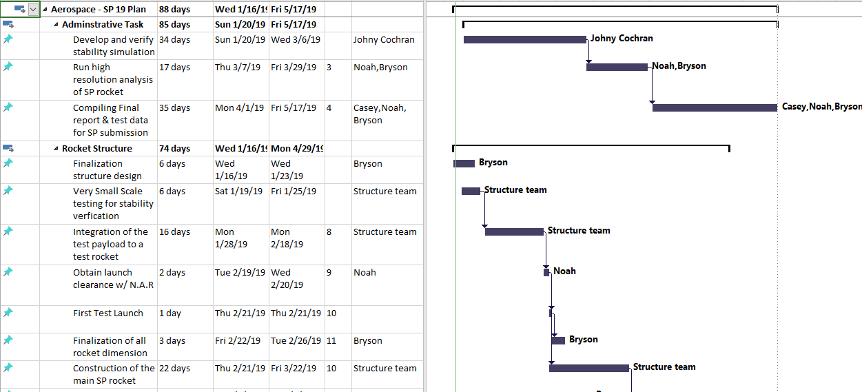
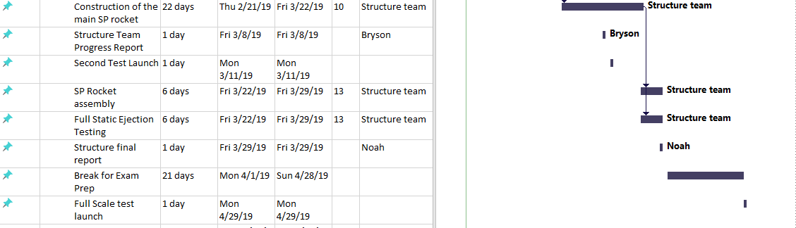
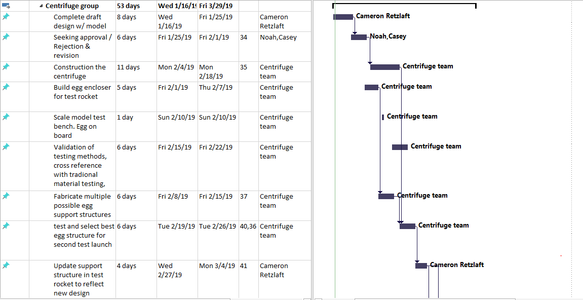
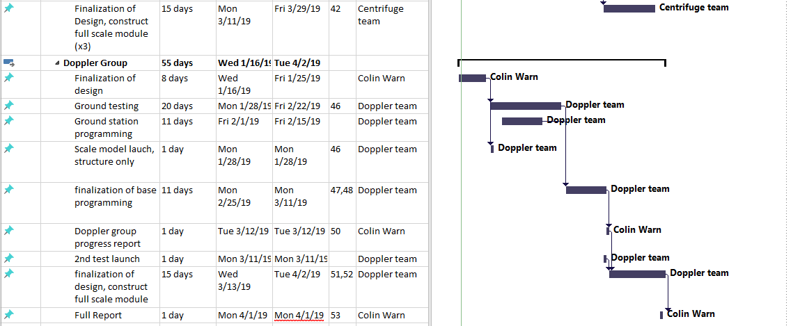
4/ Gantt Chart