Noah Thompson, Rocket Team Lead
Matthew Dickson, Control System Electronics Lead
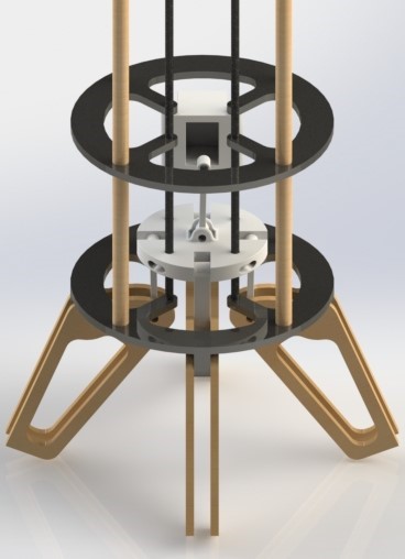 Current Air Brake Design Prototype
INTRODUCTION
In order to align objectives with the current aerospace industry and establish WSU as a contender on the world intercollegiate rocketry stage, the aerospace club is developing custom simulations and control systems for complex aerodynamic surfaces. The team’s initial design for submission to Spaceport America Cup 2019 included two payloads: a Doppler effect based velocity measurement and an egg. The club has now replaced the doppler payload with an active air brake. The original payloads were auxiliary to the primary goal of the submission, which was to serve as a test platform for the future development of aforementioned control systems. This lead to resources being removed from the original goal of the rocket. In late January the decision was made to remove the placeholder payloads, instead pursuing a simple active braking surface directly. Given a time of only five weeks to produce a functioning prototype for test launch, the group determined that use of an airbrake on this year’s rocket would only be during ascent. The P.I.D. and simulation platform developed for this system will directly apply to later, more ambitious endeavors. With the use of such control surfaces, the club can obtain a level of trajectory control unattainable through other means.
INITIAL DESIGN
This system was considered to contain primarily only an electrical and mechanical system. The physical structure of the rocket increase (an inherent requirement of the technology’s function). The mechanical components selected also were evaluated on their relative response time, as fast adjustments will need to be made during flight. Lastly, each proposed design’s significance with regard to the current state of astronautical engineering was considered as well. The proposed designs are illustrated in Figure 1.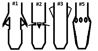
Figure 1. Considered Air-Brake Design
A weighted case study was performed, comparing each design on the criteria of mechanical simplicity, electrical simplicity, drag capabilities (ability to significantly effect overall drag), Cost, Response, and Engineering Significance (how impressive is it?). Simplicity was weighted heavily due to the time constraints. This study is summarized in the Table 1.
Table 1 – Qualitative trade study of air brake designs.
| Air Brake Trade Study | |||||
| Criteria | Weighting | #1 | #2 | #3 | #5 |
| Mech. Simplicity | 0.3 | 8 | 5 | 6 | 9 |
| Electr. Simplicity | 0.3 | 7 | 7 | 6 | 9 |
| Drag Ability | 0.1 | 10 | 10 | 2 | 2 |
| Cost | 0.1 | 3 | 4 | 4 | 7 |
| Response Speed | 0.1 | 9 | 4 | 8 | 10 |
| Relevance | 0.1 | 8 | 6 | 2 | 2 |
| TOTALS | 7.5 | 6 | 5.8 | 8.1 | |
Ultimately design five, the rotating fin section brake scored the highest in the trade study for its simplicity. However, due to its very low hypothesized drag ability, more in depth analysis of the design was performed.
Two SolidWorks flow studies of design five, one with holes open and one with holes closed, was performed. The total force against flow only increased 3N (from 230N to 233N). These preliminary findings suggest that such a drag modification device might not be significant enough for our purposes. The more traditional air brake was chosen.
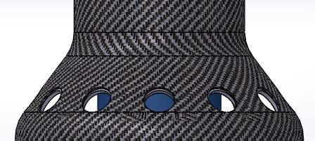
Figure 2. Rough conceptual model of design #5, ring air brake
The air brake will be designed to be so electrically and mechanically simple as possible. Almost all internal structures related to it are designed to be cut in two dimensions using a water jet (or a laser cutter for the wooden test rocket components), thus minimizing manufacturing cost and time to production. The mechanism is designed such that a single linear actuator or large servo could engage all brakes by pushing on a single platform.
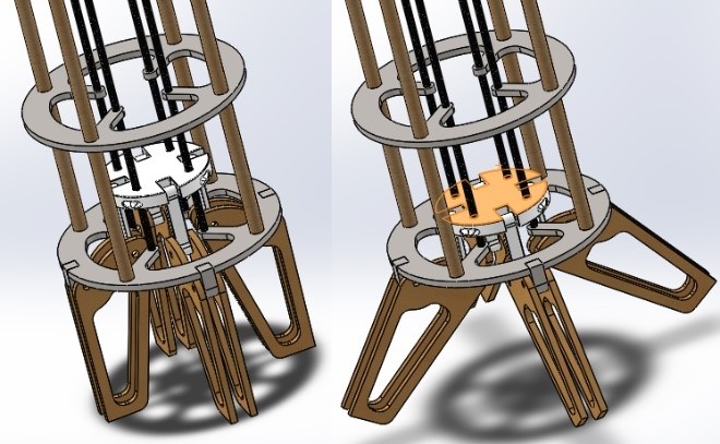 Figure 3. Base model of design #1, unoptimized, configured for test rocket. Left shown closed, right shown open
Final design and optimization for test rocket will occur from February 15th to 22nd, in tandem with test rocket primary structures fabrication and implementation of control schemes on stationary test bed.
The test rocket will have the centering rings cut from sheet metal, the center platform and linkages 3D printed with solid infill, and the fin supports will be wooden. On the spaceport model, the entirety of the structure will likely be either composite or metal, with the center structure being the only machined component.
POSSIBLE CONTROL METHODS
The design shown in this document is mostly conceptual (not yet having been optimized). The model shown is designed for a test rocket, flying to an apogee of only 100ft and meeting FAR 101 regulations. This rocket is intended for repeated launch on private land outside pullman, clear of restricted airspace. The data collected in this set of launches will be used to compare four primary frameworks for airbrake control, and two logical methods for approaching onboard data processing. The team’s goal is to minimize the amount of time necessary to run one computational cycle while maximizing altitude control accuracy. These combinations are listed below. Test rocket systems will be run off of a Teensy 3.6.
Frameworks:
“Bang-Bang” Controller – System has binary states. In the case of the airbrake, if overshoot is detected the brake will extend fully.
P-Controller – System state depends on error. The larger the error, the stronger the corrective action.
PI-Controller – System state depends on error and duration of error. The larger the error, the stronger the corrective action. In addition, if the error is too small for corrective action but is sustained, proportional corrective action will take place.
PID-Controller – System state depends on error, duration of error, and change in error. The larger the error, the stronger the corrective action. Small but sustained error will also result in a proportional corrective action. In addition, corrective action will be taken proportional to the current change in error.
Logical Methods:
Acceleration to Acceleration – The movement of the air brake is determined only by a direction and proximity to desired acceleration. The control system operates only based on acceleration response to movement, without prior knowledge of expected drag.
Acceleration to Brake Position – Desired brake position is determined as a function of needed acceleration to reach apogee. This function is created using the linear interpolation of a two dimensional coefficient of drag matrix. This dataset is generated in terms of velocity and brake position, but reparametrized in terms of average acceleration at a point.
BUDGET & TIMELINE
There is very little time to accomplish this goal, and so a strict timeline will be adhered to.
A test rocket will begin launching the weekend of March 9th, weather allowing. Design of the test rocket concludes on February 16th, with construction beginning that same weekend. The base code for the test rocket will be completed prior to the end of February. Ordering of materials for spaceport rocket fabrication will be completed upon approval, with construction beginning as soon as they arrive. The club’s updated layup technique sacrifices a small amount of weight and strength in exchange for dramatically faster turnaround and low rejection rate as compared to previous years. All rocket body tubes (and extras) should be completed within a week of construction beginning.
The full rocket will be completed in time for full scale test launch in late April, the weekend before finals. If less than three club members can be found to attend this launch, it will be postponed until late May.