Executive Summary
An innovative design in aircraft propulsion for Unmanned Aircraft Vehicles (UAV)
application using hydrogen fuel. Hydrogen fuel technology can assist in the effort of
decarbonization of the world’s economy. Team Oculus partnered with Washington State
University (WSU) Aerospace Club and Senior Mechanical Engineering Capstone to help
address Amazon’s efforts in reducing their carbon footprint and the need for a longendurance electric flight. Oculus designed a working model in MATLAB Simulink that
exhibits the behavior of the hydrogen fuel cell power system. The model can be
configured to fit required specifications and determine whether the power applied is
suitable to the load.
Introduction
The electric rotorcraft delivery industry is at a tipping point. Amazon relies heavily on
shipping packages across the world, and one of their forms of delivery is the electric
rotorcraft, also commonly known as a drone. Amazon has recently completed tests of
package delivery using conventional LIPO battery powered drones. Hydrogen fuel has a
very high specific energy, which can extend the flight duration approximately 3-5 times
over regular LIPO battery powered drones on the market. This pairing of hydrogen and
drones with Amazon is deliberate as Amazon already maintains liquid hydrogen storage
capabilities at most fulfillment centers to tend hydrogen fuel cell forklift fleets. Oculus’s
goal for this project is to model a hydrogen fueled drone that can be configurable for
Amazon and other companies that are moving towards hydrogen fueled technology.
Description of Culminating Design
Oculus has developed a model in Simulink to create the power flow of the propulsion
system and to determine the suitability and sustainability of the 1kW fuel cell for
powering the drone. The input model is constructed using a triple hybrid power system,
and consist of the following: hydrogen fuel cell, a LIPO 6s battery and a supercapacitor.
Voltage regulators are connected to both the fuel cell and the supercapacitor to
automatically maintain constant voltage output. The fuel cell will produce a constant and
steady source of power to the load while in flight. The 6s LIPO battery will produce the
instantaneous power needed to create the thrust for the drone’s initial take-off. The
supercapacitor can produce additional instantaneous power and absorb majority of the
load stress.
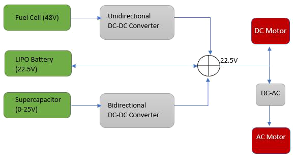
Figure 1. Propulsion System Block Diagram
Buck Converter
Due to the fuel cell having a much higher voltage than the battery, a buck
converter design (figure 3) was chosen as a step-down unidirectional DC/DC
converter. Buck converter is a class of Switch Mode Power Supply (SMPS) and
could potentially provide a vastly high-power efficiency (90%) [1].

Figure 2. Buck Converter Block Diagram
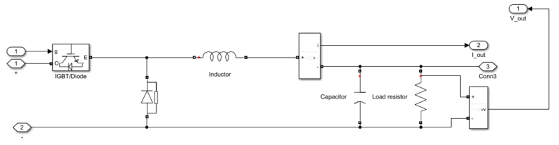
Figure 3. Buck Converter Simulink model Diagram
An IGBT transistor was chosen as a switch for the circuit due to its ability to
handle high current, and high power [2]. When the switch is on, the power supply
will connect to the inductor and the diode becomes an open circuit. Where ton
represents the time the switch is on, T = ton = + toff and D is the duty cycle as
D =ton/T. When the switch is off, the voltage across the diode will drop to zero,
the diode shunts the connection between the inductor and ground.
This led to two possible operating modes for the buck converter: continuous
mode and discontinuous mode. The continuous mode shows the behavior of the
circuit during the off state as it falls and during the on state as it rises. The output
voltage can be calculated by using the equation 1,
Vout = D * Vin (eq1)
Where D represents the duty cycle. By controlling the duty cycle, the reference
output voltage can be easily configured with a PID controller. However, during a
discontinuous mode, the behavior gets more complicated.
During the discontinuous mode, it common for a DC/DC converter to have its
inductor current fall to zero. The inductor current will not persistent enough and
will fall to zero before completing the cycle. When the peak inductor current
become less than the DC component, the diode turns on while the switch is off. If
the peak of the inductor current is bigger than the DC component, the current will
fall to zero while the diode is conducting, and the inductor current will remain
zero until the switch is back on again. This condition often happens during the
light-load condition, such as the moment before lift-off.
To control the frequency and duty cycle of the buck converter, Oculus has
designed a simple PID controller (figure 9). The PID will monitor the overall
6
voltage across all three power components and automatically regulate the
frequency to maintain and stabilize voltage levels across the system. The PID
controller regulating the voltages will prevent damage to the fuel cell and the
battery. The transfer function of the buck converter controller was calculated and
used to assist the PID.
Buck Boost Converter
To improve the power density of the drone’s power system, Oculus theorized that
the addition of a supercapacitor in parallel with the lipo-battery would reduce the
amount of power the motors drain from the battery. The main function of a
capacitor is to store electrical energy and then discharge the energy into to the
circuit when necessary. A supercapacitor is a high-capacity capacitor and could
potentially store roughly 10 to 100 times more energy per unit volume or mass
than the typical electrolytic capacitors [3]. The supercapacitor will accumulate the output energy from the lipo-battery and store
it until the system communicates to the supercapacitor to discharge the energy.
To maintain the flow of energy being stored and discharged from the
supercapacitor, Oculus decided to create a buck-boost converter to act as a
switch for the supercapacitor to the battery. A buck-boost converter is a
bidirectional DC to DC converter. A bidirectional DC to DC converter allows the
flow of power to go in both directions, which means the circuit can feed power to
the load and the load can feed the power back to the source.
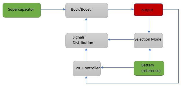
Figure 4. Buck-Boost Converter Block Diagram
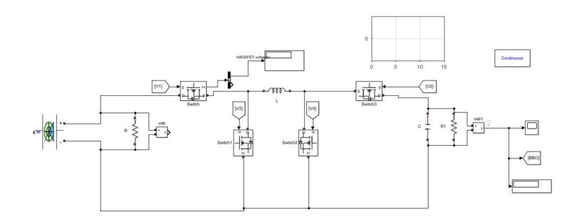
Figure 5. Buck-Boost Simulink model Diagram
Due to three additional transistors, the circuit required a more complex controller
compared to the previous design. The circuit operates on three different modes
with four different switching states (figure 6).
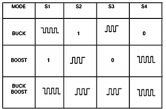
Figure 6. Switching states of the buck-boost converter
Oculus has developed a controller that can be used to control the circuit. The
mode selection circuit is a state machine that would detect the output voltage and
decide which operation mode the circuit will run on by comparing it with the
reference voltage of 22.5
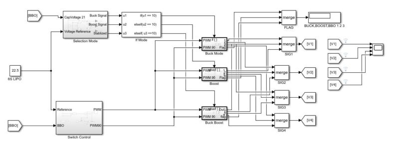
Figure 7. Control System of the Triple Hybrid Power System
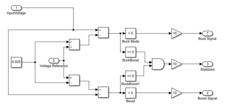
Figure 8. Selection mode
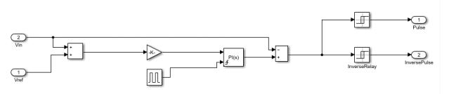
Figure 9. PID Controller
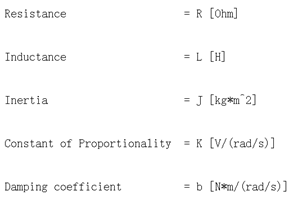
DC-AC inverter and Motor:
The nominal output for the hydrogen fuel cell drone power system should have a
stator and rotor current of 8A, a rotor speed of 1438 rpm, and an electromagnetic
torque of 1 N*m. To achieve the most efficient system, team Oculus decided to
use an AC synchronous motor. The AC synchronous motor feeds 22.5Vac of
voltage created by the DC to AC full bridge inverter, which is commonly known
as the Electrical Speed Controller (ESC) in the physical drone application. The
DC to AC inverter requires 22.5Vdc of voltage and converts to a three-phase
voltage of 22.5Vac. The inverter uses a converter to stabilize the voltage level
and is made with 6 PWM controlled diodes. The model in Simulink uses an IGBT
as diode and can be controlled with a PWM controller [4]. A PWM controller is a
pulse signal with a constant phase shift that includes 6 diodes controlled by 6
shifted pulse signals. Six diodes act as the switches by controlling the on and off
states. The output voltage frequency can also be controlled [5]. In a physical
drone application, an ESC can turn PWM controller automatically, hence, in
Simulink, team Oculus uses an open loop circuit instead of close loop circuit,
which can make a cleaner signal. The DC-AC inverter modeling is shown in Fig
10.
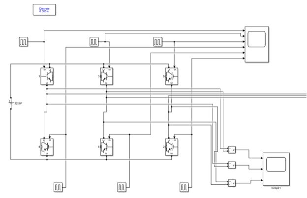
Figure 10. DC-AC inverter modeling
An AC synchronous motor is shown in fig 11, it is fed by a 3-phase voltage of
22.5Vac. A resistor in series is added to the transmission line to protect the motor
10
from burning out. By finding the correct motor parameters, team Oculus can turn
each motor parameter by experiment. For voltages under 22.5Vac or greater
than 22.5Vac, the motor will not work.
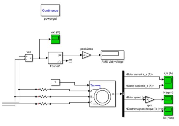
Figure 11. AC Asynchronous Motor Modeling
DC Motor Modeling
To modeling a DC motor. The rotor and shaft are assumed to be rigid. Here is the physical circuit of a DC motor.
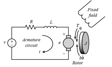
Addition information about DC motor can be found here
Analysis, Modeling and Simulation Results, Beta Prototype Test Results:
Power System
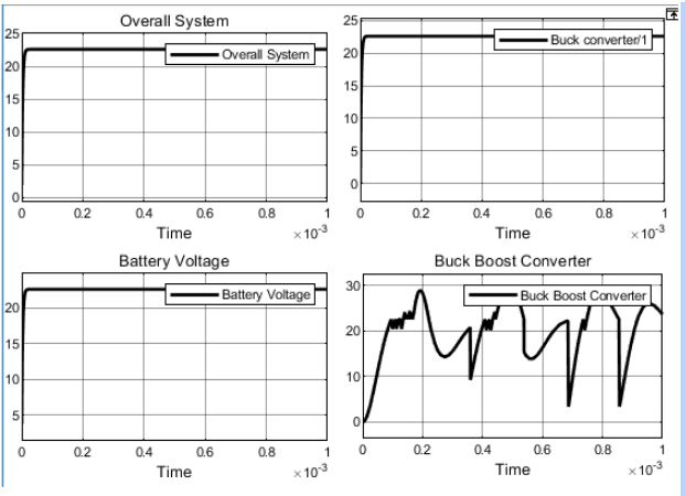
Figure 12 . Voltage level across the system.
Using the reading in figure 13 , it has indicated that the overall system has achieved the main purpose, having an overall voltage around 22.5V. The buck converter has managed to step down the input from the fuel cell at 48V to 22.58V, which is within the 0.35% of the desired voltage level.
The buck boost converter has an average output voltage at 22.5V (figure 13) with 0-25V input from the supercapacitor, however, it is still very unstable due to out of tune PID controller.
The battery voltage level maintains around 22.5V, which is the desired voltage level.
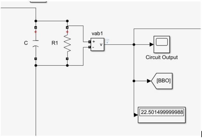
Figure 13. The Voltage reading of buck boost converter
AC Motor
The results showed that each designed circuit and block achieved team purpose. The buck converter and buck-boost converter are working functionally, and the PWM for each converter successfully receives a signal and automatically controls the converter’s mode. At this point, the voltage output of triple hybrid system can be stabilized to a voltage of 22.5Vdc. For the simulation results, team Oculus decided to monitor the stator current and rotor current to protect the motor from burning out. Moreover, the rotor speed and electromagnetic torque are two factors that reflect the motor performance. According to [6], current in stator and rotor are ideally a sine wave because of AC motor. In addition, the initial condition of an AC motor running at a constant rotor speed is specifically 1500 rpm with a no load condition (figure 15). When a load has been added, the rotor shaft starts cracking and the rotor speed must drop to go back to steady state. The final rotor speed has to be smaller than the no load speed condition. The load torque applied to the machine’s shaft is constant and is set to the nominal value of 1 N*m. The value of the machine’s shaft nominal value would be considered small because it’s easy to analyze the motor at a small value to avoid an output signal with an excess amount of noise. Simulation results are shown in the figures below.
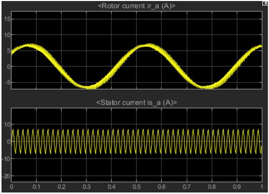
Fig 14. Rotor current (top) and stator current (bottom) of AC motor (A).
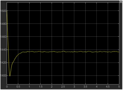
Fig 15. Rotor speed of AC motor (RPM)
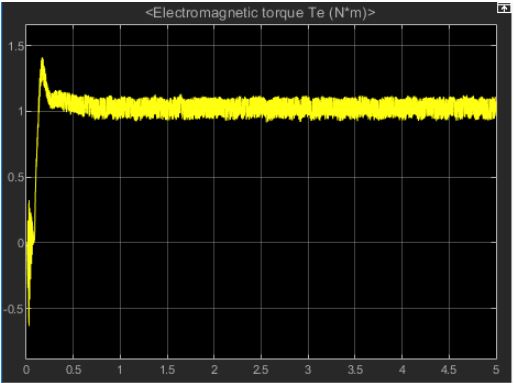
Fig 16. Electromagnetic torque of AC motor (N*m)
DC Motor
Beta Prototype Validation Results
Using the scope feature within Simulink, Oculus confirmed the overall output voltage to be 22.5V. The voltage of 22.5V is defined as the desired voltage level, in order to match the design from Protonex. The buck converter is connected to the fuel cell to step down the voltage and match the battery voltage. The two components will then in turn charge the supercapacitor. When the voltage of supercapacitor is greater than the overall voltage, the designed 4-switch buck-boost converter will then successfully step down the voltage using the buck mode of the buck-boost converter, with the help of a PID controller. Pertaining to the output of the buck-boost converter, if the battery voltage is less than the voltage of supercapacitor, boost mode of the buck-boost converter will step up the voltage. The desired voltage at 22.5Vdc of the hybrid system output is the one factor to validate the system results.
As the report mentioned, the stator current and rotor current have to be a sine wave because of AC motor, and the zero to peak current for both stator and rotor current are 7.4Aac (figure 14). In a physical application, the team could choose a motor of rated current greater than 7.4Aac without risking a burn-out of the motors. A motor running at an initial condition of 1500 rpm, when adding a load, results in a rotor speed drop to 1437 rpm (figure 15). As the report indicated before, a no load rotor speed should be the maximum case. The nominal value of torque is 1 N*m (figure 16), the simulation results match the nominal torque. The Beta prototype simulation results have been validated and accepted.
Broader Impacts and Contemporary Issues
Around the global countries are trying to reduce their carbon footprint. There has been increasing efforts in finding alternative power sources for all types of vehicles, whether they’re travelling by road, sea or air. The most common of alternative power sources would be that of solar and electrical power. However, researchers from different companies and universities have put money and time into researching the benefits of having hydrogen fuel as a power source.
According to the National Public Relations news website [7], Japan is embracing the technology of hydrogen fuel, and aims to create the first “hydrogen society”. The article gives insight into the auto companies in Japan that have plans to have 40,000 fuel cell electric vehicles on the road, with a longer-term goal of 200,000 such vehicles in the next six years.
Amazon aims to cut shipment carbon footprint in half by 2030, according to The Hill, a US political website. Amazon relies heavily on shipping packages across the globe, and ultimately aims to make all shipments carbon neutral. Amazon’s current plan to meet the carbon neutral goal, is by utilizing electric vans, using renewable energy sources such as solar power, and pushing more retailers to reuse packaging. They also hope the rise of aircraft biofuels will help aid in their plans.
Our plans for our liquid hydrogen fuel-cell-powered electric rotorcraft, will help Amazon in their goal to reduce their carbon footprint. Our power system for the electric rotorcraft is designed to extend the duration of flight to roughly 4 hours. In the event that we are successful in our design, Amazon can implement it to their future electric rotorcrafts, and be able to deliver packages to customers in a larger radius while reducing their carbon footprint.
According to the World Energy Council [8], decarbonization of energy usage is one of the biggest challenges facing industries globally. The report explains how the development of -based production and production processes in the industry can serve as a catalyst to substantial decarbonization of the economy as a whole.
Ethical Issues Affiliated with this Design
Over the past few years, surveillance drones have raised a lot of issues regarding privacy and civil liberties. Drones with advanced surveillance equipment are already in service by several law enforcement agencies to carry various activities such as live feed camera, thermal imaging to monitor US citizens. Several organizations such as the ACLU has done a lot of studies and concluded that addition laws are required to protect the citizen against unwarranted ariel surveillance. The current laws are not strong enough to ensure the technology will be used responsibly and consistently with our democratic values. In return, FAA approved new laws that would make the use of drone much easier for law enforcement agencies. Fortunately, most of those drones, with the exception of fixed-wing UAVs, operated by the military, have limited flight time duration and can only fly for roughly 20 minutes at a time. Thus prevents agencies from overusing it to monitor the citizen, and forces them to use it only when necessary. Oculus’s new propulsion design could effectively change that. Using hydrogen fuel, the surveillance capability of law enforcement could increase significantly. This might lead to police agencies abuse the technology and violate the privacy of the citizen.
The aerospace sector is heavily regulated in the United States and internationally due to security and potential safety concerns. All commercial and military aircraft must be certified as compliant to relevant safety standards by regulation body before it can fly [9]. Each electronic and electrical system design is to be verified, and physical testing is to be performed on the actual components. System output is also expected to be reviewed for the maintenance of traceability. Designs will undergo version control for all iterations and processes. Such required compliance often significantly increases the projected cost, leading to delays in production. To help minimize cost, aerospace companies often rely on model-based design. By streamlining these processes, defects can be detected during the development process, thereby preventing significantly rework and redocumentation. One of the most popular model-based design tools is Simulink. It is often considered to be the best design environment for complicated systems, and as such widely used by the aerospace sector [9]. Oculus’s design is capable of being used by researchers towards hydrogen fuel cell applications, by companies such as Protonix helping to further development of the Hydrogen fuel cell system, or amazon, providing them with a new case-study alternative propulsion system for their delivery drones. Future engineering and researching teams will be able to share their models with others in a format which facilitates the meeting of complex requirements, thus prevent additional research and development costs.
Limitations and Recommendations
Oculus still has limitations that could be improve by future teams. The first limitation would be due to the lack of computing capability of each members’ computer systems. The buck-boost converter contains a closed loop PID controller that ran multiple different PWM signals simultaneously at a frequency of 60kHz. For 1 second of simulation, it took between 2 to 3.5 hours in real time for Oculus’ s computers to run all the necessary computations, and 2 seconds of simulations is required to predict the system behavior. Thus, Oculus was unable to stabilize the buck-boost circuit. Fortunately, when running all three components in parallel, the entire system was able to stabilize the overall voltage, but the slow computation time is still an issue. The complete Beta Prototype needs to be running separately to provide the audience with a complete picture of the model.
The first part of the prototype is the triple hybrid power system and the second part is the DC-AC inverter, DC motor, and AC motor. To connect first part with the second part, the first part needs to achieve an output voltage of 22.5Vdc, and from there, team Oculus can use the 22.5Vdc output as a source input for part 2. Team Oculus can successfully run the simulation model in Simulink. The PID controller is not easy to turn, team Oculus spent lot of time turning parameters of PID controller. To stabilize the output torque, current and rotor speed, they had to find the correct parameters of the motor and those parameters depended on the system load, input voltage, an input torque. Team Oculus suggested that finding the desired motor for the system was required, and once the motor had been chosen, the RLC values of the motor could be determined in Simulink. Adding the PID controller to the AC motor allowed team Oculus to only consider changing the PID value, because the RLC values were fixed. Oculus recommends using a computer with additional computational RAM.
In conclusion, the power system works as intended with the overall voltage across each component hovering around 22.5V. The system is still not completely stable, due to the limitation of available computational RAM. If provided better computers, Oculus would have been able to tune up the PID controllers and stabilized the system.
Comparing DC and AC motor behaviors, it was obvious that the DC motor needed more current to initiate the start of the load, which indicates that a larger sized motor was needed. The current of AC motor is 8A which is more acceptable, and with the same input voltage of 22.5Vdc an AC motor can run faster and more efficient.
For the future work of Oculus’s model, there is still work to be done to tuned up and further the stabilization of the entire system, and a physical testbench will be needed to be built for additional research. Oculus has already purchase and acquired several physical components such as a battery, motors, ESCs, a buck converter, a buck boost converter and a controller for the buck-boost converter. With doing more research, the possibility of parameter matching of DC and AC motors will increase, which will result in the RLC values of two motors to be the same. In addition, the DC-AC inverter can apply close loop application if needed.
Team Oculus would like to extend its deepest thanks to mentors Dr. Jacob Leachman, Dr. Colin Merriman, and members from the Hyper Lab for the guidance provided throughout the design process.
[1] S. A. Lopa, S. Hossain, M. K. Hasan, and T. K. Chakraborty, “Design and Simulation of DC-DC Converters – irjet.net.” [Online]. Available: https://www.irjet.net/archives/V3/i1/IRJET-V3I111.pdf. [Accessed: 16-Apr-2019].
[2] A. S. Martyanov, D. V. Korobatov, and E. V. Solomin, “Research of IGBT-transistor in pulse switch,” 2016 2nd International Conference on Industrial Engineering, Applications and Manufacturing (ICIEAM), 2016.
[3] W. Raza, F. Ali, N. Raza, Y. Luo, K.-H. Kim, J. Yang, and S. Kumar, “Recent advancements in supercapacitor technology,” Research Gate. Available: https://www.researchgate.net/publication/326929552_Recent_Advancements_in_Supercapacitor_Technology/download
[4] R. E. Turkington, “Analysis of 3-phase inverter with resistive load,” Electrical Engineering, vol. 70, no. 12, pp. 1076–1076, 1951.
[5] PULSE WIDTH MODULATED INVERTER. [Online]. Available: https://www.ewh.ieee.org/soc/es/Nov1998/08/PWMINV.HTM
[6] Y. Gong, “Modeling and simulation of asynchronous motor based on MATLAB/Simulink,” 2011 International Conference on Electrical and Control Engineering, 2011.
[7] S. Phillips, “Japan Is Betting Big on the Future of Hydrogen Cars,” NPR, 18-Mar-2019. [Online]. Available: https://www.npr.org/2019/03/18/700877189/japan-is-betting-big-on-the-future-of-hydrogen-cars?fbclid=IwAR2ZiwPprMsNZGjKeeUn7CLFwHJaTIPOEMMkF8Ro1FqzPaf0icP2QYpIzZo. [Accessed: 17-Apr-2019].
[8] J. Owen-Jones, “The World Energy Council publishes hydrogen report,” Gas World, Feb. 2019
[9] “Model-based design facilitates compliance to aerospace standards,” Military & Aerospace Electronics, 01-Mar-2010. [Online]. Available: https://www.militaryaerospace.com/articles/print/volume-21/issue-3/departments/opinion/model-based-design-facilitates-compliance-to-aerospace-standards.html. [Accessed: 17-Apr-2019].
Summary of Agile and Waterfall Design Activities
There were two types of software development methodologies that team Oculus conducted. The methodologies were Agile Sprint and Waterfall Development. An Agile Sprint is defined as a short, time-boxed period when a team of people address complex adaptive problems to a specified framework. A Waterfall design is based on the principles of strict work organization and sequential stages. Both methodologies are effective.
Oculus set a 2-week time frame for their Agile Sprint. Day 1 & 2, Oculus appointed an Agile Sprint historian, defined their goal, appointed a Decider, clarified the Users & Stakeholders, clarified what the Users & Stakeholders wanted, and coordinated benchmarking sessions with experts in person and used articles for information. Day 3 & 4, Oculus made a list of possible subsystems that would be involved in their overall system, and individually tried to figure out problems and solution with each subsystem they listed. Day 5 & 6 consisted of reviewing each individual problem and solution design and voting for what they deemed to be the best solution to the problem. Once a workable solution was agreed upon, day 7 & 8 consisted of the team making a block diagram of the solution. Day 9 & 10, Oculus informed their client of all the things discussed in the sprint, and then took that information with the client’s feedback to create a cover letter for their professor, Dr. Pedrow. Day 9 & 10 concluded the team’s whole Agile Sprint process.
The designs discussed during the Agile Sprint were evaluated using Waterfall methods which included using a screening matrix to help the team choose the best concept. Oculus’s Waterfall development continued the Agile Sprint’s workable solution set defined by the team and worked towards building a workable model. In the beginning stages of Waterfall development, Oculus was working on a physical model of their design, but then realized that they misidentified the scope of the project, and that the mistake set them a month behind schedule. Due to the fact that they made a mistake, Oculus didn’t do too well on the Waterfall report and were on the verge of not being able to finish the Alpha Prototype in a timely manner. Another issue that Oculus came across in the Waterfall Development stage, was that they lost a member. Despite some severe setbacks, the ideas found during the Waterfall activities proved to be suitable for the Alpha Prototype and team Oculus was able to finish and present their findings. Oculus achieved the result of a successful Alpha Prototype by effectively communicating with each other and determining that building a Simulink model of a triple hybrid power system between a fuel cell, a battery and a supercapacitor was better suited for the time constraint. The idea of building a Simulink model of the triple hybrid system had proven to be effective in providing enough power for the drone and increasing the power density. By using the agile design concept of failing fast, Oculus had come up with a variety of concepts, and quickly found the most viable design.