Skip to main content Skip to navigation
Washington State University Aerospace Club

Great Team, Great Year

Club Photo (5)

It has been a great year for the WSU Aerospace Club. We have excelled in innovations, attempted new challenges, and grown even larger. This is the second year the club will be attending IREC and the WSU Aerospace Club has shown true dedication and excitement for the event. We have researched, manufactured, and tested our own propellant, which is no small task. We have created a parachute system that not only is designed and hand made, but also autonomously guided by GPS coordinates. We have created a 34″ wingspan glider that fits into a 4.5″ body tube and will autonomously glide back to the launch site with GPS coordinates. We have created a new electronic system with an upgraded arming mechanism and we have built an all carbon fiber fuselage with a stunning paint scheme.

All of this is possible due to the hard work that each of the club members put in for the past 8 months. It takes exceptional students to come in every Friday and work hard after a full week of school. This year is truly one for the books and I hope all of the members are proud of their accomplishments.

Ladies and Gentlemen, this is what makes clubs so exciting and impressive. Never stop improving and encouraging each other to conquer new challenges. You can do it!

13063139_10206628880261715_1167717231064625356_o

Crimson Fire: New Launch Date

After weeks of hard work and even more so this week, the Crimson Fire is nearly finished. Many members didn’t sleep for literally days and even though the team worked diligently to try and get the rocket ready for a flight today, we ultimately decided to wait to launch. Tests on the ejection system in addition to a couple other parts will be very beneficial for the rocket before its first flight. After all, sometimes you only get one shot with a rocket and we want to make sure that we have done everything that we can to make it safe and reliable for its maiden flight. We will make May 27th our new launch date in Mansfield at the “Fire in the Sky” event. Here are a couple photos from this morning of our rocket compared to last years, and the spectacular fin paint scheme designed by Jon Farrell.

IMG_20160423_081524 IMG_20160423_081718 IMG_20160423_082322

Meet the Crimson Fire Rocket!!!

Rocket all together!

WSU Aerospace club has been working tirelessly to get the rocket fully assembled so that the components that go into the rocket can start to be put in.Our rocket this year is 12.2 feet tall! which is almost twice the size of last year’s rocket the Carbon Cougar which was 6.5 feet tall. We have our first test launch in Mansfield, WA on April 23rd (weather depending) we hope that we can get one successful launch in before competition! We are so excited to compete in the IREC competition in Green River, Utah on June 15th! Go Cougs!

Aerodynamics/Structures Update

Aerodynamics/Structures has been doing great! Since we have figured out how to manufacture tubes with no wrinkles, we have been able to make our three body tubes.

image
Member Katlyn Struxness (5’3″) next to the bottom section of the rocket that was taken out of the oven
image
First body tube layup! This tube is one of the two 35″ tubes for the upper section of the rocket!


There are only two separation points on the rocket, which is at the nose cone and then between the upper section and lower section. We had to layup 3 tubes because the upper section is 70 inches long and wouldn’t fit in the oven to cure. What we are doing to alleviate this issue is to have a coupler that will be permanent to join the two 35 inch sections to make the full upper body section. With the couplers made the week before spring break, last weekend we were able to put all three sections of the rocket together!

All Three sections together standing in the WSU Aerospace Club room

As you can see, this is a pretty tall rocket, and this is without our nosecone and boat tail. The final height of the rocket will be 12.1 feet tall! This is a huge difference from our 2015 rocket which was 7 feet tall with a 4 inch outer diameter. With a bigger rocket we have more opportunities to be creative with our payload and recovery system (more on those components later!). We also have made half of a nosecone and will be using a joggle to join the two halves together; a joggle is like an insert for the inside of the nosecone. It will be offset on the inside of the nosecone and will be used as a guide to join the two halves together. Since the boat tail and fins have been made we really wanted to see them on the rocket so we have attached them. There are centering rings that insert into the fins from the inside of the body tube which reinforces the strength of the fins as well as holds the motor in place.

Slack for iOS Upload (1)
Fins with the centering rings
image
All body tubes, fins and boat tail assembled!

       image

The next steps for Aerodynamics/Structures are to epoxy in the coupler for the upper section, put bulkheads in the rocket (pictures to come for the bulkheads), and finish the nosecone.

Propulsion Team Update

Our solid propulsion team has been working to create and develop our own solid APCP rocket motor. Specifically, we have been reverse engineering the commercial Cessaroni M1300 motor, as we have modeled the performance of this motor according to our rocket specifications. The APCP motor fits within the competition constraints, is a powerful solid propellant, and is proven as a solid motor by NASA. We also chose the cross symbol as the grain geometry due to the thrust curve and immediate power required to get off the ground initially. We will be ordering our aluminum casing from a commercial site, which will also provide heat shielding and case parts for our motor. We decided to purchase our motor casing commercially due to the fact that creating the propellant is a complex enough task, and creating our own case and case parts would add a drastic amount of unnecessary costs, time, and complexity to our project. We have also put in efforts to locating a test site within the WSU lab spaces and also with the local fire department. In addition, we will be strongly focusing on creating processes and safety during our testing. There has been great progress and work done on our team, as we are trying to overcome one of the greatest innovations for this year’s competition. Here is a breakdown of the progress that we have made.

January: We received our materials for motor manufacturing. This included the ammonium perchlorate, aluminum powder, and iron oxide powder. From there, we went ahead and created our first batch of motors to test. Our goals for the initial tests were to successfully ignite a motor without an explosion. Although we took extra safety precautions, we were still not able to successfully ignite the motor on our first test. This prompted us to go back to the drawing board and re-assess our manufacturing process as this was what we suspected to be the flaw in our motor. By the end of the month, we had created a new batch of motors, modified our manufacturing process, coordinated with the Pullman Fire Department for a test site, and created an updated safety checklist. By the time we tested on January 31st, it was a huge success and we were able to successfully launch all 10 specimens that day. Here are some images of the test site and specimens that day:

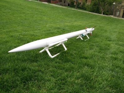
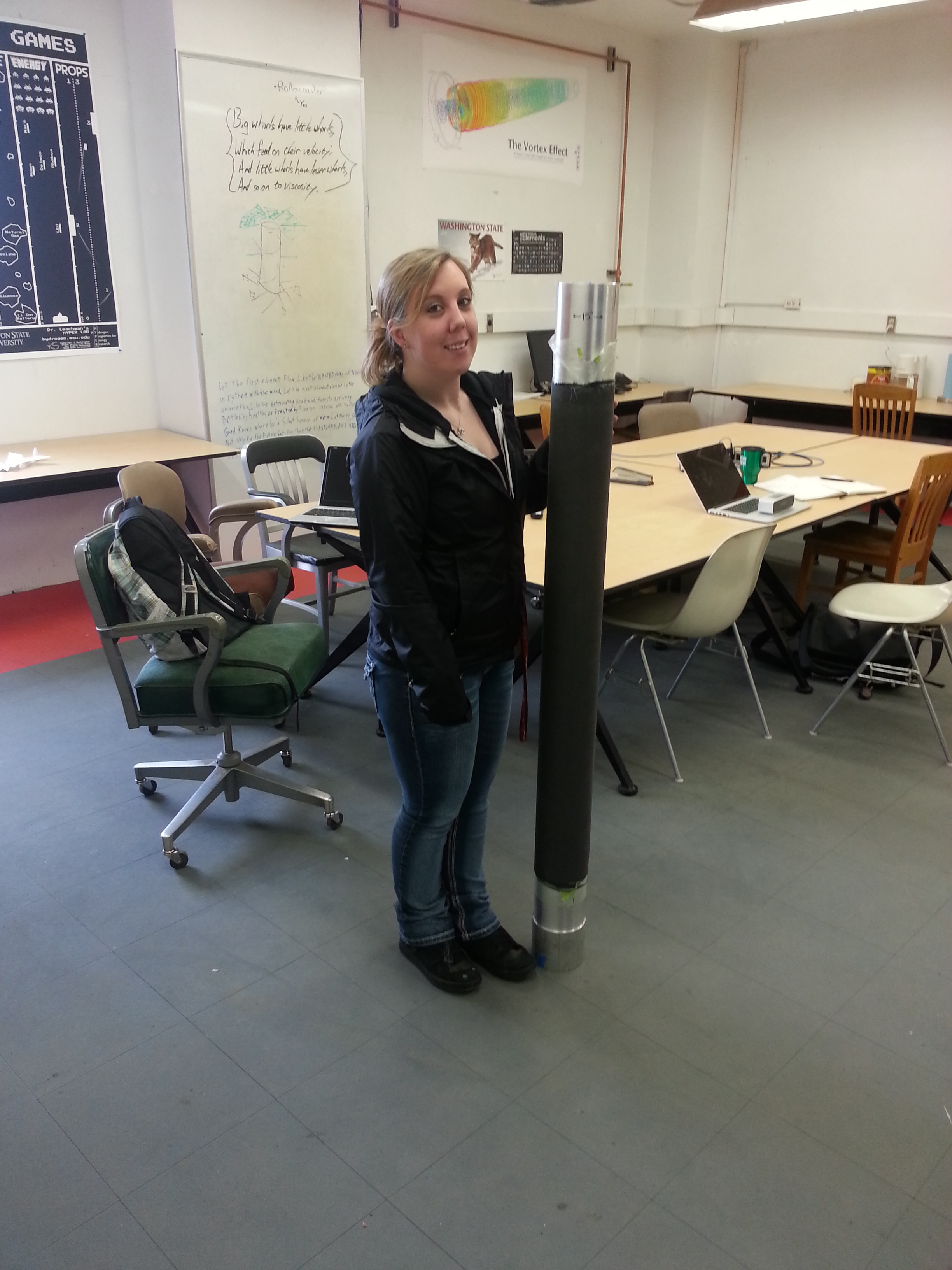
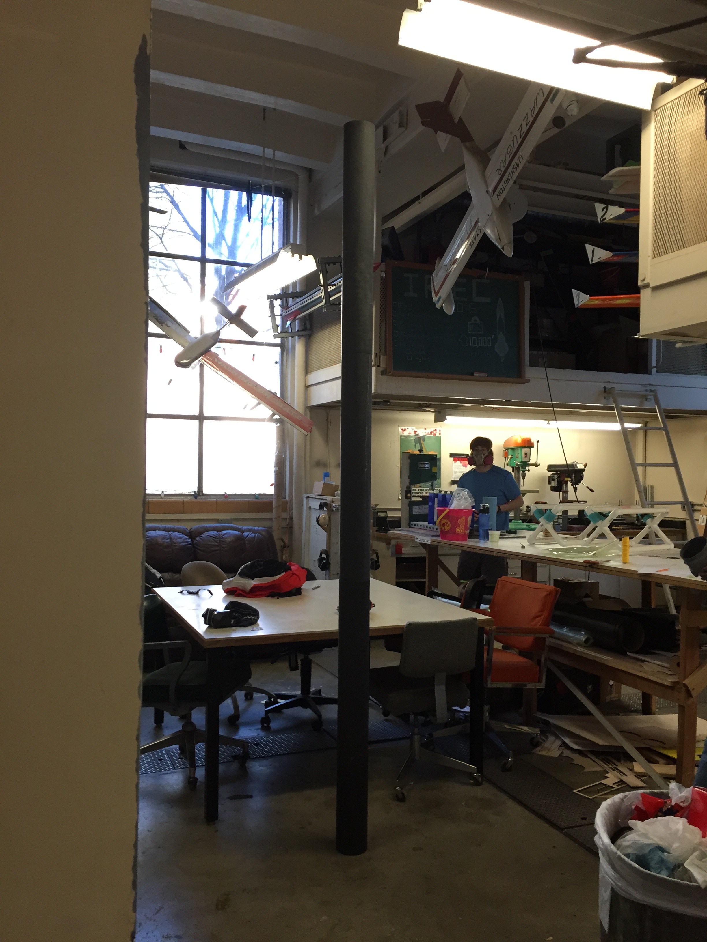
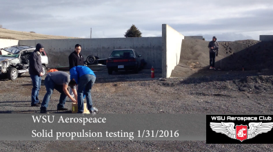
Here’s a good picture of the launch site. We used the dirt mound that our team member is standing on in the right side of the picture. This was a good, isolated section that enabled us to be far enough away from the launch.

Screen Shot 2016-03-14 at 9.22.35 PM

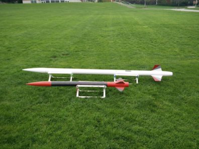
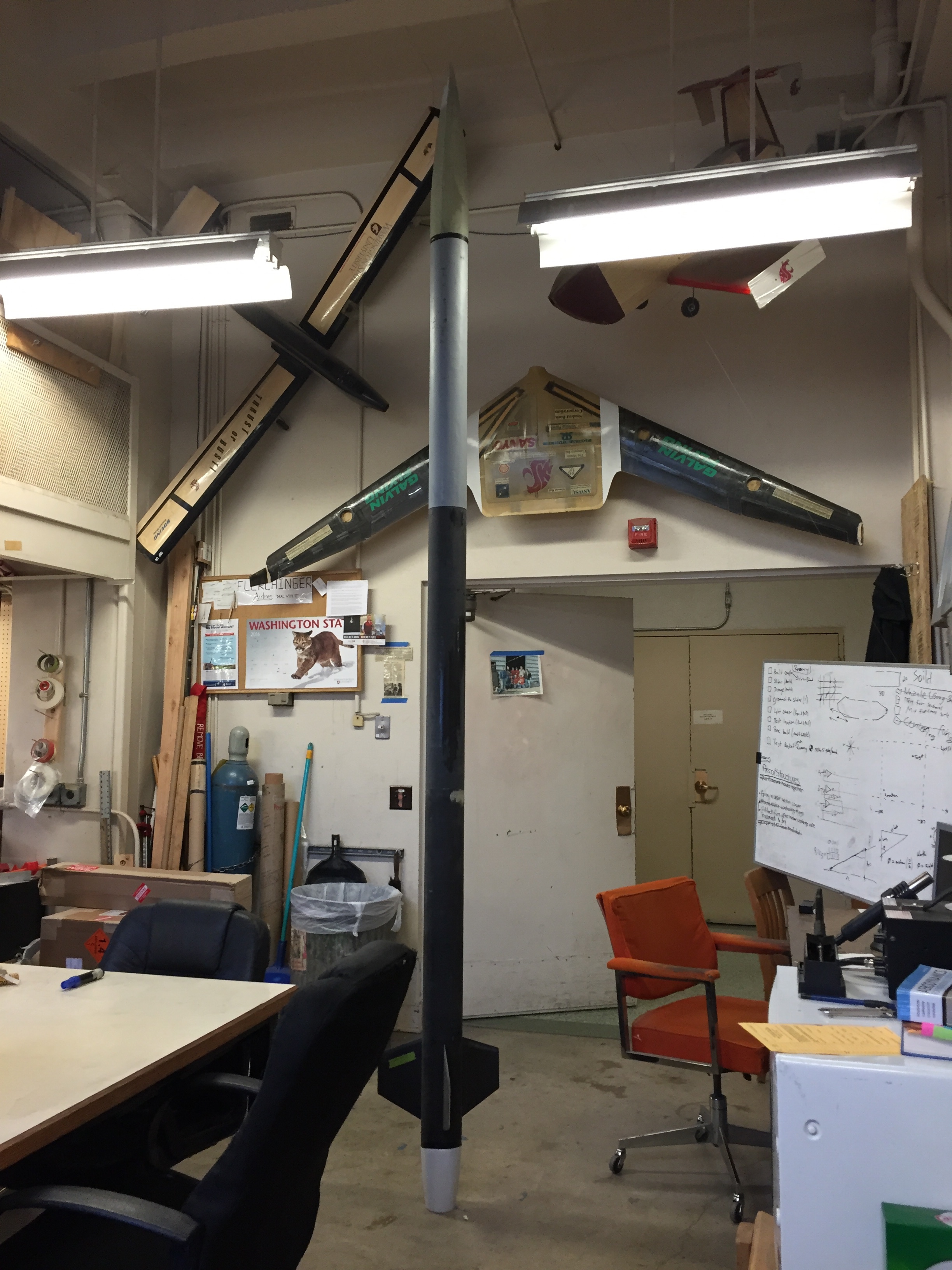
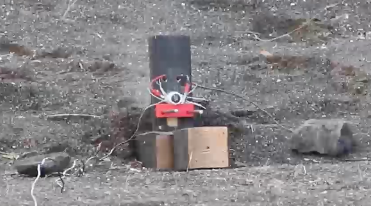
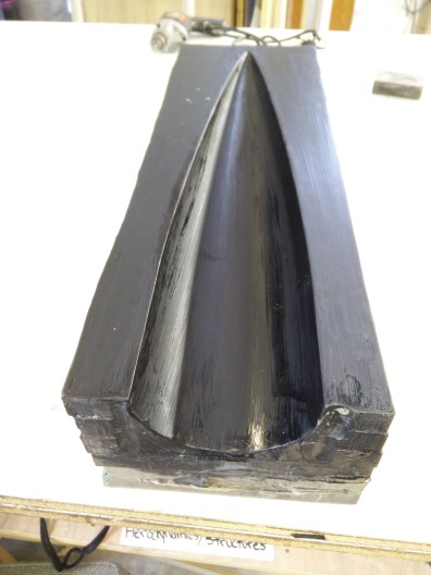
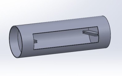
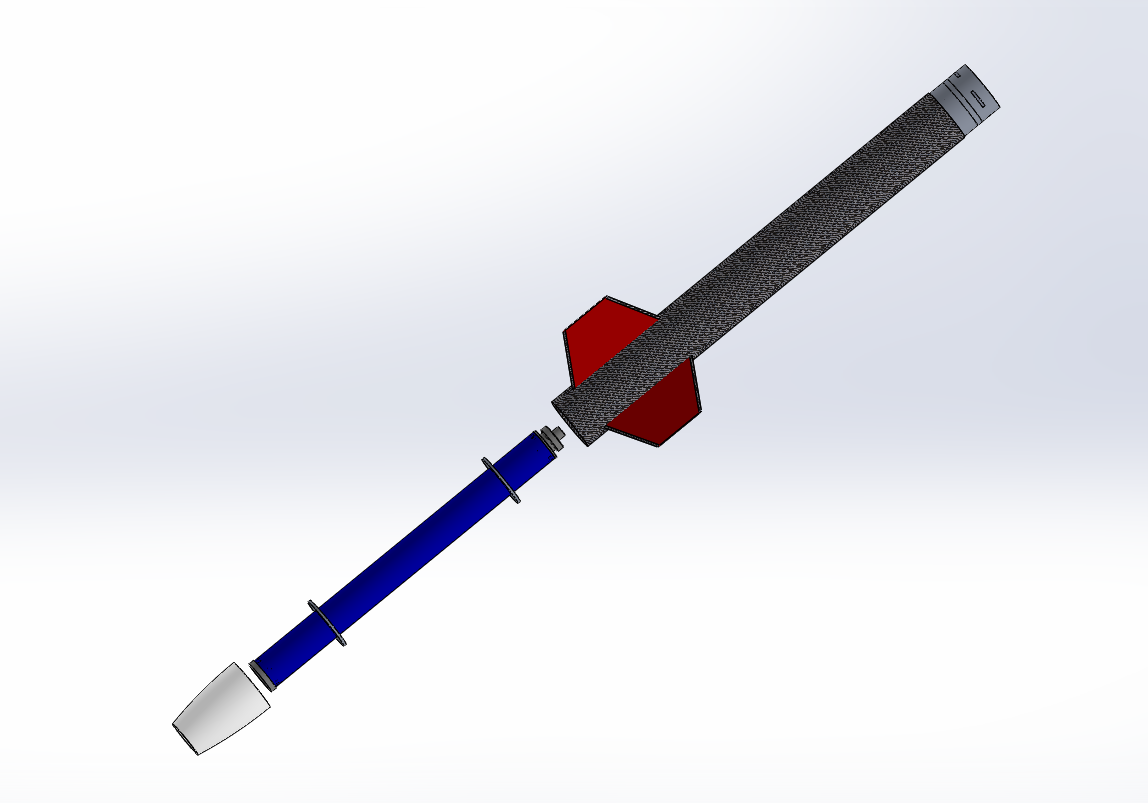
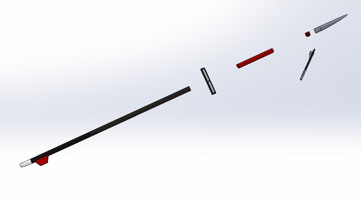
Here is a simple image of our test stand. It essentially works by inserting an igniter down the circular grain geometry. The ignitor is connected to two alligator clips that lead to our fuse box. The motor is clamped down to a 3D printed mount (the red object) and slid down the centering rods. Once we have equipped ourselves with safety gear, we went a head and ignited the motor.

Screen Shot 2016-03-14 at 9.23.16 PM

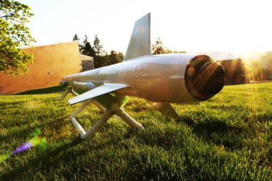
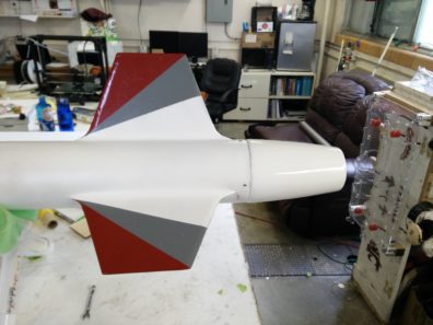
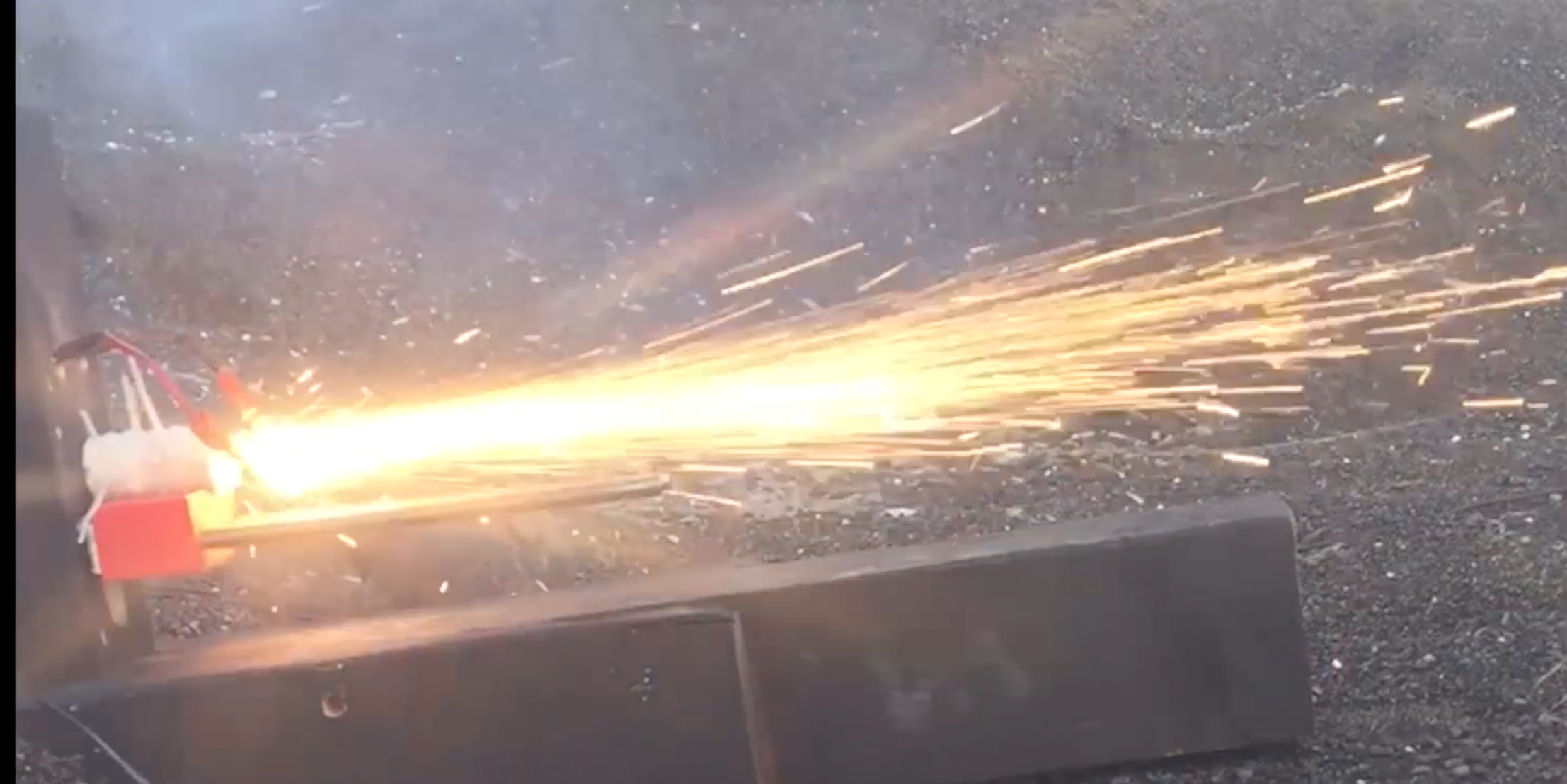
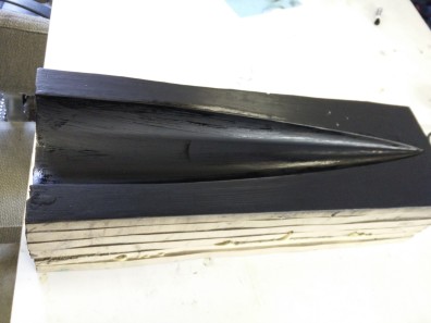
Here’s a great image of the side profile on our launch set up and our motor once it has been ignited!

Screen Shot 2016-03-14 at 9.29.10 PM

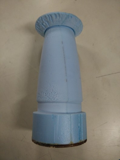
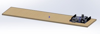
February: For this previous month, we went ahead and created a larger scale motor to see the viability of scaling up with our manufacturing process. Our tests were all successful, and we were able to take some learning points away from these tests such as additional safety precautions and further knowledge on grain geometry. Later that month, we also started the process of requesting a data acquisition system to collect data on our motor. The rest of the month was filled with modifications of the data acquisition process and adjustments to our APCP motor composition.

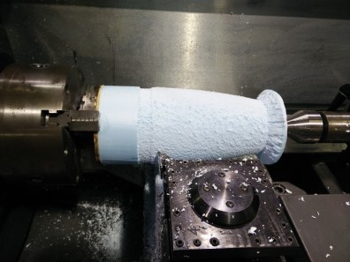
Some of our recent accomplishments include a modified test stand, finalization of our data acquisition process, and the beginning the process of manufacturing out nozzle for more detailed tests.

Aerodynamics Team Update

Aerodynamics has been working on manufacturing the fuselage tube for the past couple of weeks. A mandrel was created to hold the body tube for the layup process. They started out with a single layer of carbon fiber and vacuum bagged it. The result- fantastic layup, no wrinkles, very nice finish.

IMG_20160227_115648IMG_20160130_195218

The 2nd and 3rd layups returned less than ideal results unfortunately. 3-4 layers of CF were used for each. Each of the layers had epoxy run through them and pressed out(similar to a prepreg) before being placed on the aluminum tube. This would allow for less movement of each layer when placed onto the tube. The idea was that this would help reducing wrinkles. Each of the layups were placed into a vacuum bag and into the oven to cure. This step seemed to create the most wrinkles. Even though breather was placed around the tube, there were areas that bunched up when the vacuum sucked out all of the air. Thus, they resulted in veiny tubes. Although these can be sanded down, the process reduces the strength of the tube.

IMG_20160227_115936IMG_20160227_115842

The 4th test was great! The team had a near perfect layup. What changed?! They didn’t use the vacuum bag during the curing process. Instead, after they were done applying epoxy, peel ply was wrapped around the tube and the whole tube went to cure in the oven. The ending result looked spot on. Zero wrinkles and and smooth finish. The thickness with 3 layers was close to .1″.

IMG_20160227_115905

The Von Kármán nose cone was chosen for its low drag and high volume characteristics from subsonic to supersonic. The Von karma shape is a common nosecone profile in rockets of this size. The nosecone mold has been CNC’d and already had a test layup.

IMG_20160127_174115

Gelcoat was applied 7 times and sanded and smoothed with each added layer. Now, its so smooth that you can practically see your reflection.
IMG_20160227_120022 IMG_20160227_115952

A boat tail is being used to improve the overall aerodynamic shape of the rocket and reduce the amount of drag. The boat tail is also being used to hold the motor casing in the rocket. Initially, the mold started out as turned down foam, was sanded multiple times, filled, and sanded again resulting in a clean smooth surface. The foam plug was covered in layers of fiberglass followed by a carbon fiber sleeve to add strength and match the rest of the rocket.

IMG_20160120_173843IMG_20160120_181632

IMG_20160226_145237

Fin Profile- The hexagonal airfoil was chosen for its low drag performance, durability, and simplicity. Constructed out of BirchPlywood layered with Carbon Fiber.

IMG_20160226_145215


Electronics Team Update

Electronics team has been working on the schematic for the internal electronic components consisting of two stratologgers and the ignition system. Their ignition system utilizes a magnetic switch in addition to a physical switch on the outside of the fuselage to easily and safely arm the rocket. The whole system will have a large panel/door for easy access to the electronics while on the ground/launchpad and has removable internal panels to take out the entire electronics bay for more intricate work.

Bay Housing Electronics Foundation

Current Rocket Design Specs

Aerodynamics

Weight: 28lbs

Length:

  1. O-Give nosecone
  2. Trapezoidal fin
  3. Material CF for body

Propulsion

Weight: 5-7

Length: 24”

diameter: 3”

  1. Ammonium perchlorate and aluminum
  2. Commercial engine & case nozzle

Recovery

Weight: 15

Length: 36”

  1. Controllable parachute

Electronics

Weight: 3lbs

Length: 12”

  1. See Recovery Presentation

Payload

Weight: 10lbs (Glider~2lbs)

Length: 24” tube, 20” wingspan

  1. Collapsable autonomous Glider

Hybrid Propulsion

  1. Oxidizer- nitrous oxide
  2. Nylon and HTPB

Current Preliminary Rocket Designs

Aerodynamics

  1. O-Give nosecone
  2. Trapezoidal fin
  3. Material CF for body

Propulsion

  1. Ammonium perchlorate and aluminum
  2. Commercial engine & case nozzle

Recovery

  1. Controllable parachute

Electronics

  1. See Recovery Presentation

Payload

  1. Collapsable autonomous Glider

Hybrid Propulsion

  1. Oxidizer- nitrous oxide
  2. Nylon and HTPB